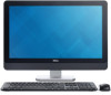

Owner's Manual
Page 3
... Memory...13 Removing the VESA Mount Bracket...13 Installing the VESA Mount Bracket...14 Removing the Power and On-Screen Display (OSD) Buttons Board 14 Installing the Power and On-Screen Display (OSD) Buttons Board 15 Removing the System-Board Shield...15 Installing the System-Board Shield...16 Removing the Converter Board...
... Memory...13 Removing the VESA Mount Bracket...13 Installing the VESA Mount Bracket...14 Removing the Power and On-Screen Display (OSD) Buttons Board 14 Installing the Power and On-Screen Display (OSD) Buttons Board 15 Removing the System-Board Shield...15 Installing the System-Board Shield...16 Removing the Converter Board...

Owner's Manual
Page 4
... Sink (Graphics Card)...34 Installing the Heat Sink (Graphics Card)...35 Removing the Antenna Module...36 Installing the Antenna Module...37 Removing the Display Panel...37 Installing the Display Panel...39 Removing the Camera...40 Installing the Camera...41 3 System Setup...43 Boot Sequence...43 Navigation Keys...43 System Setup Options...44... Setup Password...53 Assigning a System Password and Setup Password 54 Deleting or Changing an Existing System and/or Setup Password 54 4 Technical Specifications...57 5 Contacting Dell...63
... Sink (Graphics Card)...34 Installing the Heat Sink (Graphics Card)...35 Removing the Antenna Module...36 Installing the Antenna Module...37 Removing the Display Panel...37 Installing the Display Panel...39 Removing the Camera...40 Installing the Camera...41 3 System Setup...43 Boot Sequence...43 Navigation Keys...43 System Setup Options...44... Setup Password...53 Assigning a System Password and Setup Password 54 Deleting or Changing an Existing System and/or Setup Password 54 4 Technical Specifications...57 5 Contacting Dell...63

Owner's Manual
Page 10
speakers 11. power-button and on a flat surface, display side facing downwards. 3. Place the computer on -screen display (OSD) buttons board 17. input/output (I/O) board shield 12. power-supply fan bracket 14. intrusion switch 15. optical drive Removing the VESA Stand 1. WLAN card ...
speakers 11. power-button and on a flat surface, display side facing downwards. 3. Place the computer on -screen display (OSD) buttons board 17. input/output (I/O) board shield 12. power-supply fan bracket 14. intrusion switch 15. optical drive Removing the VESA Stand 1. WLAN card ...

Owner's Manual
Page 14
... the computer. 3. Removing the Power and On-Screen Display (OSD) Buttons Board 1. Remove the: a) VESA stand b) back cover 3. Follow the procedures in After Working Inside Your Computer. Disconnect the cable from the and power and on -screen display (OSD) buttons board from the chassis. 14 Install the...: a) back cover b) VESA stand 4. Lift the power and on -screen display (OSD) buttons board. Align and place the bracket on the back of the...
... the computer. 3. Removing the Power and On-Screen Display (OSD) Buttons Board 1. Remove the: a) VESA stand b) back cover 3. Follow the procedures in After Working Inside Your Computer. Disconnect the cable from the and power and on -screen display (OSD) buttons board from the chassis. 14 Install the...: a) back cover b) VESA stand 4. Lift the power and on -screen display (OSD) buttons board. Align and place the bracket on the back of the...

Owner's Manual
Page 15
...that secure the system-board shield to the power and on the computer. 2. Align and place the power and on-screen display (OSD) buttons board on -screen display (OSD) buttons board. 3. Follow the procedures in Before Working Inside Your Computer. 2. Installing the Power and On-Screen... Display (OSD) Buttons Board 1. Remove the: a) VESA stand b) back cover c) VESA mount bracket 3. Connect the cable to the computer. Follow the...
...that secure the system-board shield to the power and on the computer. 2. Align and place the power and on-screen display (OSD) buttons board on -screen display (OSD) buttons board. 3. Follow the procedures in Before Working Inside Your Computer. 2. Installing the Power and On-Screen... Display (OSD) Buttons Board 1. Remove the: a) VESA stand b) back cover c) VESA mount bracket 3. Connect the cable to the computer. Follow the...

Owner's Manual
Page 32
... Board 1. Lift and remove the system board from the chassis. Remove the screws that are connected to the computer. 5. System Board Layout The following image displays the system board layout of the computer. 32 Follow the procedures in Before Working Inside Your Computer. 2. Disconnect all the cables that secure the system...
... Board 1. Lift and remove the system board from the chassis. Remove the screws that are connected to the computer. 5. System Board Layout The following image displays the system board layout of the computer. 32 Follow the procedures in Before Working Inside Your Computer. 2. Disconnect all the cables that secure the system...

Owner's Manual
Page 36
... Follow the procedures in Before Working Inside Your Computer. 2. d) input/output (I /O) board shield f) WLAN card g) optical drive h) hard drive i) intrusion switch j) power and on-screen display (OSD) buttons board k) converter board l) processor fan m) power supply unit n) heat-sink assembly o) power-supply fan p) system board 3. Removing the Antenna Module 1.
... Follow the procedures in Before Working Inside Your Computer. 2. d) input/output (I /O) board shield f) WLAN card g) optical drive h) hard drive i) intrusion switch j) power and on-screen display (OSD) buttons board k) converter board l) processor fan m) power supply unit n) heat-sink assembly o) power-supply fan p) system board 3. Removing the Antenna Module 1.

Owner's Manual
Page 37
...output (I /O) board shield m) system-board shield n) VESA mount bracket o) back cover p) VESA stand 4. Place the antenna module on -screen display (OSD) buttons board k) converter board l) power-supply fan m) power supply unit n) heat-sink assembly o) processor fan p) speakers q) antenna ...2. Install: a) system board b) power-supply fan c) heat-sink assembly d) power supply unit e) processor fan f) converter board g) power and on-screen display (OSD) buttons board h) intrusion switch i) hard drive j) optical drive k) WLAN card l) input/output (I /O) board shield f) WLAN card g) optical ...
...output (I /O) board shield m) system-board shield n) VESA mount bracket o) back cover p) VESA stand 4. Place the antenna module on -screen display (OSD) buttons board k) converter board l) power-supply fan m) power supply unit n) heat-sink assembly o) processor fan p) speakers q) antenna ...2. Install: a) system board b) power-supply fan c) heat-sink assembly d) power supply unit e) processor fan f) converter board g) power and on-screen display (OSD) buttons board h) intrusion switch i) hard drive j) optical drive k) WLAN card l) input/output (I /O) board shield f) WLAN card g) optical ...

Owner's Manual
Page 38
Disconnect the LVDS cable from the chassis. 38 Lift the display panel from the display panel. For touch computers, the display panel should be disassembled in a clean-room environment. 3. Remove any other cables or antennae around the edges of the base panel. 4. NOTE: These instructions are valid only for non-touch computers. Remove the screws that secure the base panel to the chassis. Lift the base panel from the chassis. 5.
Disconnect the LVDS cable from the chassis. 38 Lift the display panel from the display panel. For touch computers, the display panel should be disassembled in a clean-room environment. 3. Remove any other cables or antennae around the edges of the base panel. 4. NOTE: These instructions are valid only for non-touch computers. Remove the screws that secure the base panel to the chassis. Lift the base panel from the chassis. 5.

Owner's Manual
Page 39
Tighten the screws to secure the display bracket to the chassis. 5. Place the display panel on the chassis. 4. Tighten the screws to secure the base panel to the display panel. 2. Install: a) system board b) antenna module c) speakers d) processor fan e) heat-sink assembly 39 Installing the Display Panel 1. Place the base panel on the chassis. 3. Connect the LVDS cable to the display panel. 6. Remove the screws that secure the display bracket to the display panel. 6. Remove the display bracket from the display panel.
Tighten the screws to secure the display bracket to the chassis. 5. Place the display panel on the chassis. 4. Tighten the screws to secure the base panel to the display panel. 2. Install: a) system board b) antenna module c) speakers d) processor fan e) heat-sink assembly 39 Installing the Display Panel 1. Place the base panel on the chassis. 3. Connect the LVDS cable to the display panel. 6. Remove the screws that secure the display bracket to the display panel. 6. Remove the display bracket from the display panel.
Owner's Manual
Page 40
... n) input/output (I /O) board shield f) WLAN card g) optical drive h) hard drive i) intrusion switch j) power and on-screen display (OSD) buttons board k) converter board l) processor fan m) power supply unit n) heat-sink assembly o) power-supply fan p) system board q) display panel 3. Remove the: a) VESA stand b) back cover c) VESA mount bracket d) system-board shield e) input/output (I /O) board...
... n) input/output (I /O) board shield f) WLAN card g) optical drive h) hard drive i) intrusion switch j) power and on-screen display (OSD) buttons board k) converter board l) processor fan m) power supply unit n) heat-sink assembly o) power-supply fan p) system board q) display panel 3. Remove the: a) VESA stand b) back cover c) VESA mount bracket d) system-board shield e) input/output (I /O) board...

Owner's Manual
Page 41
Connect the camera cable and fix the latch. 3. Follow the procedures in After Working Inside Your Computer. 41 Tighten the screws to secure the camera to the chassis. 2. Install: a) display panel b) system board c) power-supply fan d) heat-sink assembly e) power supply unit f) processor fan g) converter board h) power and on-screen display (OSD) buttons board i) intrusion switch j) hard drive k) optical drive l) WLAN card m) input/output (I/O) board shield n) system-board shield o) VESA mount bracket p) back cover q) VESA stand 4. Installing the Camera 1.
Connect the camera cable and fix the latch. 3. Follow the procedures in After Working Inside Your Computer. 41 Tighten the screws to secure the camera to the chassis. 2. Install: a) display panel b) system board c) power-supply fan d) heat-sink assembly e) power supply unit f) processor fan g) converter board h) power and on-screen display (OSD) buttons board i) intrusion switch j) hard drive k) optical drive l) WLAN card m) input/output (I/O) board shield n) system-board shield o) VESA mount bracket p) back cover q) VESA stand 4. Installing the Camera 1.

Owner's Manual
Page 43
...example: optical drive or hard drive). Down arrow Moves to the next field. 43 During the Power-on Self Test (POST), when the Dell logo appears, you can: • Access System Setup by pressing key • Bring up the one-time boot menu by pressing key The...Removable Drive (if available) • STXXXX Drive NOTE: XXX denotes the SATA drive number. • Optical Drive • Diagnostics NOTE: Choosing Diagnostics, will display the ePSA diagnostics screen. From the System Setup, you can boot from including the diagnostic option. NOTE: For most of the system setup options, changes...
...example: optical drive or hard drive). Down arrow Moves to the next field. 43 During the Power-on Self Test (POST), when the Dell logo appears, you can: • Access System Setup by pressing key • Bring up the one-time boot menu by pressing key The...Removable Drive (if available) • STXXXX Drive NOTE: XXX denotes the SATA drive number. • Optical Drive • Diagnostics NOTE: Choosing Diagnostics, will display the ePSA diagnostics screen. From the System Setup, you can boot from including the diagnostic option. NOTE: For most of the system setup options, changes...
Owner's Manual
Page 44
..., and 64-Bit Technology. • Device Information - The options are Legacy and UEFI. NOTE: For the standard graphics browser only. Displays Memory Installed, Memory Available, Memory Speed, Memory Channels Mode, Memory Technology, DIMM A Size, DIMM B Size. • PCI Information ...Controller Audio Controller, Wi-Fi Device, Bluetooth Device. The list options are : • Boot Sequence - General Option System Information Description Displays the following information: • System Information - By default, the Windows Boot Manager check box is selected. Boot Sequence Allows you ...
..., and 64-Bit Technology. • Device Information - The options are Legacy and UEFI. NOTE: For the standard graphics browser only. Displays Memory Installed, Memory Available, Memory Speed, Memory Channels Mode, Memory Technology, DIMM A Size, DIMM B Size. • PCI Information ...Controller Audio Controller, Wi-Fi Device, Bluetooth Device. The list options are : • Boot Sequence - General Option System Information Description Displays the following information: • System Information - By default, the Windows Boot Manager check box is selected. Boot Sequence Allows you ...

Owner's Manual
Page 51
... Direct I /O must be enabled when the computer boots. Specifies whether keyboard related errors are : • Minimal • Thorough - Specifies whether the sign-on screen displays a message, that displays the keystroke sequence required to use this feature. • Trusted Execution - Table 10. Wireless Option Wireless Device Enable Description Allows enabling/disabling the internal...
... Direct I /O must be enabled when the computer boots. Specifies whether keyboard related errors are : • Minimal • Thorough - Specifies whether the sign-on screen displays a message, that displays the keystroke sequence required to use this feature. • Trusted Execution - Table 10. Wireless Option Wireless Device Enable Description Allows enabling/disabling the internal...

Owner's Manual
Page 52
Cloud Desktop Option Server Lookup Method Server IP Address Server Port Client Address Method Client IP Address Client Subnet Mask Client Gateway 52 Description Displays the service tag of the client. Controls the SERR message mechanism. The options are : • Static IP - This option is selected by default. This option ...
Cloud Desktop Option Server Lookup Method Server IP Address Server Port Client Address Method Client IP Address Client Subnet Mask Client Gateway 52 Description Displays the service tag of the client. Controls the SERR message mechanism. The options are : • Static IP - This option is selected by default. This option ...

Owner's Manual
Page 53
... appears. 12. Go to locate or find your preferred download method in the System Configuration group is not enabled. System Logs Option BIOS events Description Displays the system event log and allows you are unable to...
... appears. 12. Go to locate or find your preferred download method in the System Configuration group is not enabled. System Logs Option BIOS events Description Displays the system event log and allows you are unable to...

Owner's Manual
Page 55
... password and press or . Press to save the changes and exit from the System Setup. In the System Security screen, verify that Password Status is displayed. 2. If you change the System and/or Setup password, re-enter the new password when promoted. To enter the System Setup, press immediately after a power...
... password and press or . Press to save the changes and exit from the System Setup. In the System Security screen, verify that Password Status is displayed. 2. If you change the System and/or Setup password, re-enter the new password when promoted. To enter the System Setup, press immediately after a power...

Owner's Manual
Page 57
...Table 15. 4 Technical Specifications NOTE: Offerings may vary by region. Table 14. Video Feature Video Controller (Integrated) Video Memory External Display Support Specification Integrated Intel HD Graphics 4600 (4th generation Core i3/i5/i7 DC/QC CPUs), AMD Radeon HD8750A (optional discrete video ...solution) shared memory VGA, HDMI, and Wi-Fi display NOTE: Wi-Fi display requires a wireless card which must be purchased separately. 57 For more information regarding the configuration of your computer, click Start (...
...Table 15. 4 Technical Specifications NOTE: Offerings may vary by region. Table 14. Video Feature Video Controller (Integrated) Video Memory External Display Support Specification Integrated Intel HD Graphics 4600 (4th generation Core i3/i5/i7 DC/QC CPUs), AMD Radeon HD8750A (optional discrete video ...solution) shared memory VGA, HDMI, and Wi-Fi display NOTE: Wi-Fi display requires a wireless card which must be purchased separately. 57 For more information regarding the configuration of your computer, click Start (...
Owner's Manual
Page 58
Audio Feature Controller Speaker Internal speaker amplifier Internal microphone support Volume controls Table 18. Displays Feature Type Maximum resolution Refresh rate Brightness Operating angle Pixel pitch Controls Table 21. RW or combo Blu-ray writer Drives Feature Hard drive... 10/100/1000 Mbps Ethernet LAN on system board • half mini-card (Wi-Fi b/g/n supporting Wi-Fi display) • combo half mini-card (Bluetooth 4.0 and Wi-Fi b/g/n supporting Wi-Fi display) Specification one Specification 23-inch full-HD WLED 1920 x 1080 60 Hz Brightness up/down buttons 178 horizontal / ...
Audio Feature Controller Speaker Internal speaker amplifier Internal microphone support Volume controls Table 18. Displays Feature Type Maximum resolution Refresh rate Brightness Operating angle Pixel pitch Controls Table 21. RW or combo Blu-ray writer Drives Feature Hard drive... 10/100/1000 Mbps Ethernet LAN on system board • half mini-card (Wi-Fi b/g/n supporting Wi-Fi display) • combo half mini-card (Bluetooth 4.0 and Wi-Fi b/g/n supporting Wi-Fi display) Specification one Specification 23-inch full-HD WLED 1920 x 1080 60 Hz Brightness up/down buttons 178 horizontal / ...


