
Owner's Manual
Page 3
... 9 System Overview...9 Removing the VESA Stand...10 Installing the VESA Stand...11 Removing the Back Cover...11 Installing the Back Cover...12 Removing the Memory...12 Installing the Memory...13 Removing the VESA Mount Bracket...13 Installing the VESA Mount Bracket...14 Removing the Power and On-Screen Display (OSD) Buttons Board...
... 9 System Overview...9 Removing the VESA Stand...10 Installing the VESA Stand...11 Removing the Back Cover...11 Installing the Back Cover...12 Removing the Memory...12 Installing the Memory...13 Removing the VESA Mount Bracket...13 Installing the VESA Mount Bracket...14 Removing the Power and On-Screen Display (OSD) Buttons Board...

Owner's Manual
Page 9
hard drive 4. coin-cell battery 6. System Overview Figure 1. power supply unit (PSU) 2. heat sink 8. memory module 9 camera 3. Inside View 1. heat sink assembly 7. 2 Removing and Installing Components This section provides detailed information on how to remove or install the components from your computer. processor fan 5.
hard drive 4. coin-cell battery 6. System Overview Figure 1. power supply unit (PSU) 2. heat sink 8. memory module 9 camera 3. Inside View 1. heat sink assembly 7. 2 Removing and Installing Components This section provides detailed information on how to remove or install the components from your computer. processor fan 5.
Owner's Manual
Page 12
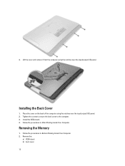
Tighten the screws to secure the back cover to the computer. 3. Follow the procedures in After Working Inside Your Computer. Remove the: a) VESA stand b) back cover 12 Installing the Back Cover 1. Install the VESA stand. 4. Follow the procedures in Before Working Inside Your Computer. 2. Removing the Memory 1. Place the cover on the back of the computer using the notches near the input/output (I /O) panel. 4. Lift the cover and remove it from the computer using the notches near the input/output (I /O) panel. 2.
Tighten the screws to secure the back cover to the computer. 3. Follow the procedures in After Working Inside Your Computer. Remove the: a) VESA stand b) back cover 12 Installing the Back Cover 1. Install the VESA stand. 4. Follow the procedures in Before Working Inside Your Computer. 2. Removing the Memory 1. Place the cover on the back of the computer using the notches near the input/output (I /O) panel. 4. Lift the cover and remove it from the computer using the notches near the input/output (I /O) panel. 2.

Owner's Manual
Page 13
...bracket to secure them in the system-board connector. 2. 3. Place the memory shield back into its connector. Installing the Memory 1. Follow the procedures in Before Working Inside Your Computer. 2. Align the notch on the memory module until it pops-up. Remove the: a) VESA stand b) back ...cover 3. Lift the bracket away from the memory module until the release tabs spring back to the computer. Install the: a) back...
...bracket to secure them in the system-board connector. 2. 3. Place the memory shield back into its connector. Installing the Memory 1. Follow the procedures in Before Working Inside Your Computer. 2. Align the notch on the memory module until it pops-up. Remove the: a) VESA stand b) back ...cover 3. Lift the bracket away from the memory module until the release tabs spring back to the computer. Install the: a) back...

Owner's Manual
Page 32
.... 5. Follow the procedures in Before Working Inside Your Computer. 2. Removing the System Board 1. Remove the: a) VESA stand b) back cover c) VESA mount bracket d) system-board shield e) memory f) optical drive g) hard drive h) heat-sink assembly i) power supply unit j) input/output (I/O) board shield k) converter board l) power-supply fan 3.
.... 5. Follow the procedures in Before Working Inside Your Computer. 2. Removing the System Board 1. Remove the: a) VESA stand b) back cover c) VESA mount bracket d) system-board shield e) memory f) optical drive g) hard drive h) heat-sink assembly i) power supply unit j) input/output (I/O) board shield k) converter board l) power-supply fan 3.

Owner's Manual
Page 34
... Working Inside Your Computer. 2. Follow the procedures in After Working Inside Your Computer. Remove the: a) VESA stand b) back cover c) VESA mount bracket d) system-board shield e) memory f) optical drive g) hard drive h) heat-sink assembly i) power supply unit j) input/output (I /O) board shield d) power supply unit e) heat-sink assembly f) hard drive g) optical drive...
... Working Inside Your Computer. 2. Follow the procedures in After Working Inside Your Computer. Remove the: a) VESA stand b) back cover c) VESA mount bracket d) system-board shield e) memory f) optical drive g) hard drive h) heat-sink assembly i) power supply unit j) input/output (I /O) board shield d) power supply unit e) heat-sink assembly f) hard drive g) optical drive...

Owner's Manual
Page 36
... the: a) VESA stand b) back cover c) VESA mount bracket d) system-board shield e) input/output (I /O) board shield e) power supply unit f) heat-sink assembly g) hard drive h) optical drive i) memory j) system-board shield k) VESA mount bracket l) back cover m) VESA stand 5. Remove the screws that secure the antenna module to the chassis. Follow the procedures in...
... the: a) VESA stand b) back cover c) VESA mount bracket d) system-board shield e) input/output (I /O) board shield e) power supply unit f) heat-sink assembly g) hard drive h) optical drive i) memory j) system-board shield k) VESA mount bracket l) back cover m) VESA stand 5. Remove the screws that secure the antenna module to the chassis. Follow the procedures in...
Owner's Manual
Page 44
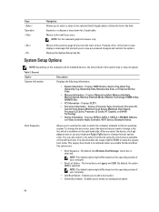
... previous page till you to save any unsaved changes and restarts the system. Displays the System Setup help file. Displays Memory Installed, Memory Available, Memory Speed, Memory Channels Mode, Memory Technology, DIMM A Size, DIMM B Size. • PCI Information - You can also select or de-select from...in the field. Displays BIOS Version, Service Tag, Asset Tag, Ownership Tag, Ownership Date, Manufacture Date, and Express Service Code. • Memory Information - Expands or collapses a drop‐down arrows or use your computer. • Boot List Option - By default, the option ...
... previous page till you to save any unsaved changes and restarts the system. Displays the System Setup help file. Displays Memory Installed, Memory Available, Memory Speed, Memory Channels Mode, Memory Technology, DIMM A Size, DIMM B Size. • PCI Information - You can also select or de-select from...in the field. Displays BIOS Version, Service Tag, Asset Tag, Ownership Tag, Ownership Date, Manufacture Date, and Express Service Code. • Memory Information - Expands or collapses a drop‐down arrows or use your computer. • Boot List Option - By default, the option ...
Owner's Manual
Page 46
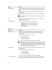
... password • Enter the new password • Confirm the new password The successful changes in the BIOS setup irrespective of USB mass storage devices (HDD, memory key, floppy). The drive does not have a password set by default. • Disable Media Card Description This field lets you delete the admin password, the...
... password • Enter the new password • Confirm the new password The successful changes in the BIOS setup irrespective of USB mass storage devices (HDD, memory key, floppy). The drive does not have a password set by default. • Disable Media Card Description This field lets you delete the admin password, the...

Owner's Manual
Page 48
... • Replace from a user-selected file 48 The options are : • PK • KEK • db • dbx If you access the Option Read Only Memory (OROM) configuration screens via the hotkey. After the boot, the setting will revert to the Intel RAID (CTRL+I) or Intel Management Engine BIOS Extension (CTRL...
... • Replace from a user-selected file 48 The options are : • PK • KEK • db • dbx If you access the Option Read Only Memory (OROM) configuration screens via the hotkey. After the boot, the setting will revert to the Intel RAID (CTRL+I) or Intel Management Engine BIOS Extension (CTRL...

Owner's Manual
Page 57
...i3 / i5 / i7 series Total cache Chipset Up to view information about your computer. Video Feature Video Controller (Integrated) Video Memory External Display Support Specification Integrated Intel HD Graphics 4600 (4th generation Core i3/i5/i7 DC/QC CPUs), AMD Radeon HD8750A (...HDMI, and Wi-Fi display NOTE: Wi-Fi display requires a wireless card which must be purchased separately. 57 Memory Feature Type Connectors Capacity Minimum Memory Maximum Memory Specification up to 1600 MHz, unbuffered non-ECC, dual‑channel DDR3L configuration two internally-accessible DDR3L SODIMM sockets 2...
...i3 / i5 / i7 series Total cache Chipset Up to view information about your computer. Video Feature Video Controller (Integrated) Video Memory External Display Support Specification Integrated Intel HD Graphics 4600 (4th generation Core i3/i5/i7 DC/QC CPUs), AMD Radeon HD8750A (...HDMI, and Wi-Fi display NOTE: Wi-Fi display requires a wireless card which must be purchased separately. 57 Memory Feature Type Connectors Capacity Minimum Memory Maximum Memory Specification up to 1600 MHz, unbuffered non-ECC, dual‑channel DDR3L configuration two internally-accessible DDR3L SODIMM sockets 2...

Setup And Features Information Tech Sheet
Page 2
optical drive eject button 9. USB 3.0 connectors (2) 6. microphone connector 7. display 7. On-Screen Display (OSD) buttons (3) 10. Back View 1. camera LED 5. power button 12. back panel connectors 2. memory card reader 2 5. stand Figure 2. security cable slot 3. optical drive (optional) Back View 8. VESA cover 4. microphone (right) NOTE: The location of microphone varies in the non-touch version. 6. hard-drive activity light 11. headphone connector 4.
optical drive eject button 9. USB 3.0 connectors (2) 6. microphone connector 7. display 7. On-Screen Display (OSD) buttons (3) 10. Back View 1. camera LED 5. power button 12. back panel connectors 2. memory card reader 2 5. stand Figure 2. security cable slot 3. optical drive (optional) Back View 8. VESA cover 4. microphone (right) NOTE: The location of microphone varies in the non-touch version. 6. hard-drive activity light 11. headphone connector 4.

Statement of Volatility
Page 1
... BIOS and Video BIOS for correct operation of data) Embedded U9425 96K bytes non-volatile memory. Power off system Media Card - Stores CMOS information. Dell Optiplex 9020 AIO CAUTION: A CAUTION indicates either potential damage to hardware or loss of Volatility - The Dell OptiPlex 9020 AIO contains both volatile and non-volatile (NV) components. Table 1. The following NV components are...
... BIOS and Video BIOS for correct operation of data) Embedded U9425 96K bytes non-volatile memory. Power off system Media Card - Stores CMOS information. Dell Optiplex 9020 AIO CAUTION: A CAUTION indicates either potential damage to hardware or loss of Volatility - The Dell OptiPlex 9020 AIO contains both volatile and non-volatile (NV) components. Table 1. The following NV components are...

Statement of Volatility
Page 2
User Non Volatile optical media. Yes replaceable Low level format Low level format/erase CAUTION: All other components on the memory (DDR3). SMSC is removed from the system. one. Trademarks used in GB. be SSD (solid state flash drive). Primary power loss (unplugging the power cord ... Accessible for external data Remedial Action (Action necessary to prevent loss of data) User Non Volatile magnetic media, Yes replaceable various sizes in this text: Dell™, the DELL logo, OptiPlex™ are trademarks of Standard Microsystems Corp. May also -
User Non Volatile optical media. Yes replaceable Low level format Low level format/erase CAUTION: All other components on the memory (DDR3). SMSC is removed from the system. one. Trademarks used in GB. be SSD (solid state flash drive). Primary power loss (unplugging the power cord ... Accessible for external data Remedial Action (Action necessary to prevent loss of data) User Non Volatile magnetic media, Yes replaceable various sizes in this text: Dell™, the DELL logo, OptiPlex™ are trademarks of Standard Microsystems Corp. May also -


