
User Manual
Page 2
Back View 1. memory card reader Back Panel View 5. USB 3.0 connectors (2) 6. Back Panel View 1. Back View Figure 2. VGA-out connector 4. power supply diagnostic button 2 3. back panel connectors 2. headphone connector Figure 3. power supply diagnostic light 2. security cable slot 3. microphone connector 7. line-out connector VESA cover 4.
Back View 1. memory card reader Back Panel View 5. USB 3.0 connectors (2) 6. Back Panel View 1. Back View Figure 2. VGA-out connector 4. power supply diagnostic button 2 3. back panel connectors 2. headphone connector Figure 3. power supply diagnostic light 2. security cable slot 3. microphone connector 7. line-out connector VESA cover 4.

User Manual
Page 4
.... Voltaje de alimentación Frecuencia 100 VAC - 240 VAC 50 Hz - 60 Hz 4 The following information is calculated by using the power supply wattage rating. Figure 7. Physical Width Height Depth: Without stand With stand Weight: Without stand With stand 574.00 mm (22.60 inches)...240 VAC 200 W 4774 BTU/hr NOTE: Heat dissipation is provided on the device described in this document in compliance with your computer. Power Coin-cell battery Voltage Wattage Maximum heat dissipation 3 V CR2032 lithium coin cell 100 VAC to 95 °F) Information para NOM (únicamente...
.... Voltaje de alimentación Frecuencia 100 VAC - 240 VAC 50 Hz - 60 Hz 4 The following information is calculated by using the power supply wattage rating. Figure 7. Physical Width Height Depth: Without stand With stand Weight: Without stand With stand 574.00 mm (22.60 inches)...240 VAC 200 W 4774 BTU/hr NOTE: Heat dissipation is provided on the device described in this document in compliance with your computer. Power Coin-cell battery Voltage Wattage Maximum heat dissipation 3 V CR2032 lithium coin cell 100 VAC to 95 °F) Information para NOM (únicamente...
Owner's Manual
Page 3
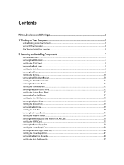
... Switch...17 Installing the Intrusion Switch...18 Removing the Wireless Local Area Network (WLAN) Card 18 Installing the WLAN Card...19 Removing the Power-Supply Fan...19 Installing the Power-Supply Fan...20 Removing the Power Supply Unit (PSU)...20 Installing the Power Supply Unit...21 Removing the Heat-Sink Assembly...22 Installing the Heat-Sink Assembly...22
... Switch...17 Installing the Intrusion Switch...18 Removing the Wireless Local Area Network (WLAN) Card 18 Installing the WLAN Card...19 Removing the Power-Supply Fan...19 Installing the Power-Supply Fan...20 Removing the Power Supply Unit (PSU)...20 Installing the Power Supply Unit...21 Removing the Heat-Sink Assembly...22 Installing the Heat-Sink Assembly...22

Owner's Manual
Page 19
... bracket to the system board. 3. Align and place the WLAN card on the connector. 2. Follow the procedures in Before Working Inside Your Computer. 2. Removing the Power-Supply Fan 1. Remove the: a) VESA stand b) back cover c) VESA mount bracket d) system-board shield 3. Installing the WLAN Card 1. Tighten the screws to secure the WLAN card... to the chassis. Lift the fan bracket away from the computer. 19 Connect the WLAN cables. 4. Remove the screw that secure the power-supply fan to it's chassis and lift it away from the computer. 4.
... bracket to the system board. 3. Align and place the WLAN card on the connector. 2. Follow the procedures in Before Working Inside Your Computer. 2. Removing the Power-Supply Fan 1. Remove the: a) VESA stand b) back cover c) VESA mount bracket d) system-board shield 3. Installing the WLAN Card 1. Tighten the screws to secure the WLAN card... to the chassis. Lift the fan bracket away from the computer. 19 Connect the WLAN cables. 4. Remove the screw that secure the power-supply fan to it's chassis and lift it away from the computer. 4.

Owner's Manual
Page 20
Press the tab and disconnect the power-supply cable from the computer. 3. Installing the Power-Supply Fan 1. Install: a) system-board shield b) VESA mount bracket c) back cover d) VESA stand 5. Follow the procedures in the computer. 20 Align .... 2. Follow the procedures in After Working Inside Your Computer. Removing the Power Supply Unit (PSU) 1. Remove the: a) VESA stand b) back cover c) VESA mount bracket d) system-board shield e) input/output board shield f) power-supply fan 3. Place the power-supply fan on the system board. Tighten the screw to secure the fan bracket...
Press the tab and disconnect the power-supply cable from the computer. 3. Installing the Power-Supply Fan 1. Install: a) system-board shield b) VESA mount bracket c) back cover d) VESA stand 5. Follow the procedures in the computer. 20 Align .... 2. Follow the procedures in After Working Inside Your Computer. Removing the Power Supply Unit (PSU) 1. Remove the: a) VESA stand b) back cover c) VESA mount bracket d) system-board shield e) input/output board shield f) power-supply fan 3. Place the power-supply fan on the system board. Tighten the screw to secure the fan bracket...

Owner's Manual
Page 21
Installing the Power Supply Unit 1. Remove the screws securing the power supply unit to the chassis. 3. Place the power supply unit on the hooks in the computer. 4. Tighten the screws to secure the power supply unit to the chassis. Install: a) power-supply fan b) input/output board shield c) system-board shield d) VESA mount bracket e) back cover f) VESA stand 21 Thread the cable on the computer. 2. 4. Connect the power-supply cable to the connector on the system board. 5. Lift the PSU up and remove it from the computer.
Installing the Power Supply Unit 1. Remove the screws securing the power supply unit to the chassis. 3. Place the power supply unit on the hooks in the computer. 4. Tighten the screws to secure the power supply unit to the chassis. Install: a) power-supply fan b) input/output board shield c) system-board shield d) VESA mount bracket e) back cover f) VESA stand 21 Thread the cable on the computer. 2. 4. Connect the power-supply cable to the connector on the system board. 5. Lift the PSU up and remove it from the computer.

Owner's Manual
Page 22
... Computer. Tighten the screws to secure the heat-sink assembly to the chassis. 6. Remove the: a) VESA stand b) back cover c) VESA mount bracket d) system-board shield e) power-supply fan 3. Installing the Heat-Sink Assembly 1.
... Computer. Tighten the screws to secure the heat-sink assembly to the chassis. 6. Remove the: a) VESA stand b) back cover c) VESA mount bracket d) system-board shield e) power-supply fan 3. Installing the Heat-Sink Assembly 1.

Owner's Manual
Page 25
Place the input/output board shield on the computer. 6. Pass the power connector and fix it to the input/output shield. 5. Install: a) power-supply fan b) system-board shield c) VESA mount bracket d) back cover e) VESA stand 7. Follow the procedures in After Working Inside Your Computer. Remove the: a) VESA stand b) back ...
Place the input/output board shield on the computer. 6. Pass the power connector and fix it to the input/output shield. 5. Install: a) power-supply fan b) system-board shield c) VESA mount bracket d) back cover e) VESA stand 7. Follow the procedures in After Working Inside Your Computer. Remove the: a) VESA stand b) back ...

Owner's Manual
Page 29
... Speakers 1. Remove the: a) VESA stand b) back cover c) VESA mount bracket d) system-board shield e) memory f) optical drive g) hard drive h) heat-sink assembly i) power supply unit j) input/output board shield k) converter board l) power-supply fan 3. Tighten the screws to secure the speaker to the connector on the system board. 3. Disconnect any cables connected to the computer...
... Speakers 1. Remove the: a) VESA stand b) back cover c) VESA mount bracket d) system-board shield e) memory f) optical drive g) hard drive h) heat-sink assembly i) power supply unit j) input/output board shield k) converter board l) power-supply fan 3. Tighten the screws to secure the speaker to the connector on the system board. 3. Disconnect any cables connected to the computer...

Owner's Manual
Page 30
Lift and remove the system board from the chassis. Place the system board on the computer. 2. Tighten the screws to secure the system board to the base panel. 3. Installing the System Board 1. Install: a) power-supply fan b) converter board c) input/output board shield d) power supply unit e) heat-sink assembly f) hard drive g) optical drive h) memory i) system-board shield 30 5.
Lift and remove the system board from the chassis. Place the system board on the computer. 2. Tighten the screws to secure the system board to the base panel. 3. Installing the System Board 1. Install: a) power-supply fan b) converter board c) input/output board shield d) power supply unit e) heat-sink assembly f) hard drive g) optical drive h) memory i) system-board shield 30 5.
Owner's Manual
Page 31
...: a) VESA stand b) back cover c) VESA mount bracket d) system-board shield e) input/output board shield f) WLAN card g) optical drive h) hard drive i) intrusion switch j) power-button board k) converter board l) power-supply fan m) power supply unit n) heat-sink assembly o) processor fan p) speakers q) antenna module r) system board NOTE: These instructions are valid only for non-touch computers. Remove the...
...: a) VESA stand b) back cover c) VESA mount bracket d) system-board shield e) input/output board shield f) WLAN card g) optical drive h) hard drive i) intrusion switch j) power-button board k) converter board l) power-supply fan m) power supply unit n) heat-sink assembly o) processor fan p) speakers q) antenna module r) system board NOTE: These instructions are valid only for non-touch computers. Remove the...

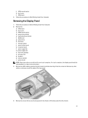
Owner's Manual
Page 33
Installing the Display Panel 1. Place the display panel on the chassis. 4. Install: a) system board b) antenna module c) speakers d) system board e) processor fan f) heat-sink assembly g) power supply unit h) power-supply fan i) converter board j) power-button board k) intrusion switch l) hard drive m) optical drive n) WLAN card o) input/output board shield p) system-board shield q) VESA mount bracket r) back cover s) VESA...
Installing the Display Panel 1. Place the display panel on the chassis. 4. Install: a) system board b) antenna module c) speakers d) system board e) processor fan f) heat-sink assembly g) power supply unit h) power-supply fan i) converter board j) power-button board k) intrusion switch l) hard drive m) optical drive n) WLAN card o) input/output board shield p) system-board shield q) VESA mount bracket r) back cover s) VESA...

Owner's Manual
Page 34
...secure the antenna module to the chassis 3. Installing the Antenna Modules 1. Install: a) system board b) power-supply fan c) heat-sink assembly d) power supply unit e) processor fan 34 Place the antenna module on the chassis. 2. Follow the procedures in Before ... shield e) input/output board shield f) WLAN card g) optical drive h) hard drive i) intrusion switch j) power button board k) converter board l) processor fan m) power supply unit n) heat-sink assembly o) power-supply fan p) system board 3. Removing the Antenna Modules 1. Tighten the screws to secure the antenna module to ...
...secure the antenna module to the chassis 3. Installing the Antenna Modules 1. Install: a) system board b) power-supply fan c) heat-sink assembly d) power supply unit e) processor fan 34 Place the antenna module on the chassis. 2. Follow the procedures in Before ... shield e) input/output board shield f) WLAN card g) optical drive h) hard drive i) intrusion switch j) power button board k) converter board l) processor fan m) power supply unit n) heat-sink assembly o) power-supply fan p) system board 3. Removing the Antenna Modules 1. Tighten the screws to secure the antenna module to ...

Owner's Manual
Page 35
... b) back cover c) VESA mount bracket d) system-board shield e) input/output board shield f) WLAN card g) optical drive h) hard drive i) intrusion switch j) power button board k) converter board l) processor fan m) power supply unit n) heat-sink assembly o) power-supply fan p) system board q) display panel 3. Lift the latch and disconnect the camera cable. Remove the screws that secure the camera...
... b) back cover c) VESA mount bracket d) system-board shield e) input/output board shield f) WLAN card g) optical drive h) hard drive i) intrusion switch j) power button board k) converter board l) processor fan m) power supply unit n) heat-sink assembly o) power-supply fan p) system board q) display panel 3. Lift the latch and disconnect the camera cable. Remove the screws that secure the camera...

Owner's Manual
Page 36
Install: a) display panel b) system board c) power-supply fan d) heat-sink assembly e) power supply unit f) processor fan g) converter board h) power-button board i) intrusion switch j) hard drive k) optical drive l) WLAN card m) input/output board shield n) system-board shield o) VESA mount bracket p) back cover q) VESA stand 4. Follow the procedures in After Working Inside Your Computer. 36 Connect the camera cable and fix the latch. 3. Tighten the screws to secure the camera to the chassis. 2. Installing the Camera 1.
Install: a) display panel b) system board c) power-supply fan d) heat-sink assembly e) power supply unit f) processor fan g) converter board h) power-button board i) intrusion switch j) hard drive k) optical drive l) WLAN card m) input/output board shield n) system-board shield o) VESA mount bracket p) back cover q) VESA stand 4. Follow the procedures in After Working Inside Your Computer. 36 Connect the camera cable and fix the latch. 3. Tighten the screws to secure the camera to the chassis. 2. Installing the Camera 1.

Owner's Manual
Page 43
... of the system fan. • Fan Control Override (not selected) NOTE: When enabled, the fan runs at the time you specified above . • Weekdays - Power Management Option AC Recovery Auto On Time Deep Sleep Control Fan Control Override USB Wake Support Wake on by special LAN signals when it receives... a wake-up from the LAN or wireless LAN. • LAN Only - Allows the system to power up signal from the off your computer using the switch on automatically. Table 6. Does not allow the system to AC power supply.
... of the system fan. • Fan Control Override (not selected) NOTE: When enabled, the fan runs at the time you specified above . • Weekdays - Power Management Option AC Recovery Auto On Time Deep Sleep Control Fan Control Override USB Wake Support Wake on by special LAN signals when it receives... a wake-up from the LAN or wireless LAN. • LAN Only - Allows the system to power up signal from the off your computer using the switch on automatically. Table 6. Does not allow the system to AC power supply.

Owner's Manual
Page 51
.... Refer to the table below for Intel platform); Beep Description Failure Coverage 1 BIOS ROM checksum in an S4 (hibernate) or S5 (Powered Off) power state. Chipset Error Time-Of-Day Clock test failure. There may be malfunctioning or incorrectly installed. All other beep codes will be an .... Solid White The computer is blank. Diagnostic Beep Codes No POST with the system board, memory, processor or the power supply. BIOS System board failure, covers BIOS corruption or Chip ROM error 2 No RAM Detected Memory failure 3 Chipset Error (North and South ...
.... Refer to the table below for Intel platform); Beep Description Failure Coverage 1 BIOS ROM checksum in an S4 (hibernate) or S5 (Powered Off) power state. Chipset Error Time-Of-Day Clock test failure. There may be malfunctioning or incorrectly installed. All other beep codes will be an .... Solid White The computer is blank. Diagnostic Beep Codes No POST with the system board, memory, processor or the power supply. BIOS System board failure, covers BIOS corruption or Chip ROM error 2 No RAM Detected Memory failure 3 Chipset Error (North and South ...
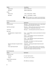
Owner's Manual
Page 56
...exists between the network and the computer. Green light - Blinking white light indicates that the computer is turned on integrated network adapter Power supply diagnostic light Specification White light - White light - Green - Feature Without stand With Stand Weight: Without stand With Stand Specification 68... 24.69 lb) NOTE: The weight of your computer may vary depending on state; Yellow - The power supply is reading data from or writing data to the power connector (at the back of the computer) and the electrical outlet. a good 1000 Mbps connection exists ...
...exists between the network and the computer. Green light - Blinking white light indicates that the computer is turned on integrated network adapter Power supply diagnostic light Specification White light - White light - Green - Feature Without stand With Stand Weight: Without stand With Stand Specification 68... 24.69 lb) NOTE: The weight of your computer may vary depending on state; Yellow - The power supply is reading data from or writing data to the power connector (at the back of the computer) and the electrical outlet. a good 1000 Mbps connection exists ...


