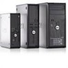
Setup and Features Information Tech Sheet (Desktop, Mini-Tower, Small Form Factor)
Page 7
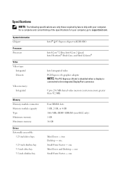
...DisplayPort connector. Specifications NOTE: The following specifications are only those required by law to ship with your computer, go to support.dell.com. For a complete and current listing of the specifications for your computer. one Small Form Factor - one Small Form Factor... - one Mini-Tower and Desktop - one System Information Chipset Processor Processor Video Video type: Integrated Discrete Video memory: Integrated Memory Memory module connector Memory module capacity Type Minimum memory Maximum memory Drives ...
...DisplayPort connector. Specifications NOTE: The following specifications are only those required by law to ship with your computer, go to support.dell.com. For a complete and current listing of the specifications for your computer. one Small Form Factor - one Small Form Factor... - one Mini-Tower and Desktop - one System Information Chipset Processor Processor Video Video type: Integrated Discrete Video memory: Integrated Memory Memory module connector Memory module capacity Type Minimum memory Maximum memory Drives ...
Setup and Features Information Tech Sheet (Ultra Small Form Factor)
Page 4
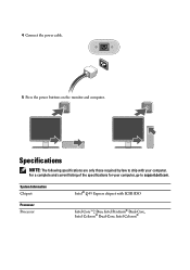
For a complete and current listing of the specifications for your computer. Specifications NOTE: The following specifications are only those required by law to support.dell.com. System Information Chipset Intel® Q45 Express chipset with your computer, go to ship with ICH10DO Processor Processor Intel Core™2 Duo, Intel Pentium® Dual-Core, Intel Celeron® Dual-Core, Intel Celeron® 4 Connect the power cable. 5 Press the power buttons on the monitor and computer.
For a complete and current listing of the specifications for your computer. Specifications NOTE: The following specifications are only those required by law to support.dell.com. System Information Chipset Intel® Q45 Express chipset with your computer, go to ship with ICH10DO Processor Processor Intel Core™2 Duo, Intel Pentium® Dual-Core, Intel Celeron® Dual-Core, Intel Celeron® 4 Connect the power cable. 5 Press the power buttons on the monitor and computer.
Service Manual
Page 3
...reverse order. As you disconnect a cable, pull on its connector or on its pull-tab, not on Your Computer Dell™ OptiPlex™ 780 Service Manual-Desktop Before Working Inside Your Computer Recommended Tools Turning Off Your Computer After Working Inside Your Computer Before Working Inside... yourself by using a wrist grounding strap or by its edges, not by periodically touching an unpainted metal surface, such as a processor by its pins. To avoid damaging your computer, perform the following safety guidelines to help protect your computer from potential damage and ...
...reverse order. As you disconnect a cable, pull on its connector or on its pull-tab, not on Your Computer Dell™ OptiPlex™ 780 Service Manual-Desktop Before Working Inside Your Computer Recommended Tools Turning Off Your Computer After Working Inside Your Computer Before Working Inside... yourself by using a wrist grounding strap or by its edges, not by periodically touching an unpainted metal surface, such as a processor by its pins. To avoid damaging your computer, perform the following safety guidelines to help protect your computer from potential damage and ...
Service Manual
Page 5
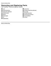
Back to Contents Page Removing and Replacing Parts Dell™ OptiPlex™ 780 Service Manual-Desktop Cover Primary Hard Drive Floppy Drive (Optional) Expansion Card Memory Power Supply Fan System Board Optical Drive Secondary Hard Drive (Optional) Riser Cage Standard Back Plate Heat Sink and Processor Coin-Cell Battery IO Panel Back to Contents Page
Back to Contents Page Removing and Replacing Parts Dell™ OptiPlex™ 780 Service Manual-Desktop Cover Primary Hard Drive Floppy Drive (Optional) Expansion Card Memory Power Supply Fan System Board Optical Drive Secondary Hard Drive (Optional) Riser Cage Standard Back Plate Heat Sink and Processor Coin-Cell Battery IO Panel Back to Contents Page
Service Manual
Page 6
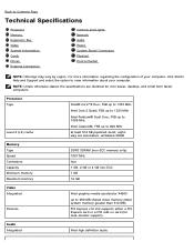
...the specifications are identical for dual-monitor support) Audio Integrated Intel high definition audio FSB up to 1066 MHz Intel Celeron®; Processor Type Level 2 (L2) cache Intel® Core™2 Duo; FSB up to 800 MHz at least 512 KB pipelined...the configuration of your computer, click Start® Help and Support and select the option to Contents Page Technical Specifications Processor Memory Expansion Bus Video System Information Cards Drives External Connectors Controls and Lights Network Audio Power System Board Connectors Physical Environmental...
...the specifications are identical for dual-monitor support) Audio Integrated Intel high definition audio FSB up to 1066 MHz Intel Celeron®; Processor Type Level 2 (L2) cache Intel® Core™2 Duo; FSB up to 800 MHz at least 512 KB pipelined...the configuration of your computer, click Start® Help and Support and select the option to Contents Page Technical Specifications Processor Memory Expansion Bus Video System Information Cards Drives External Connectors Controls and Lights Network Audio Power System Board Connectors Physical Environmental...
Service Manual
Page 9
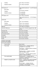
... x1 Mini-tower Desktop Small form factor PCI Express x16 Serial ATA Mini-tower Desktop Small form factor Memory Internal USB device Processor fan Hard-drive fan Front panel control Processor Power 12V Power Controls and Lights Front of the computer Power button Power light Drive activity light Network connectivity light two...
... x1 Mini-tower Desktop Small form factor PCI Express x16 Serial ATA Mini-tower Desktop Small form factor Memory Internal USB device Processor fan Hard-drive fan Front panel control Processor Power 12V Power Controls and Lights Front of the computer Power button Power light Drive activity light Network connectivity light two...
Service Manual
Page 15
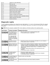
...(one module and restart the computer. If the problem persists, contact Dell. If two or more memory modules are detected, but a memory failure has occurred. Reseat any installed graphics cards. A possible processor failure has occurred. The diagnostic lights are not lit after the computer... a problem, your computer has four lights labeled 1, 2, 3, and 4 on the bank panel. If the problem persists, contact Dell. Reseat the processor (see Processor information for video ROM failure No timer tick Shutdown failure Gate A20 failure Unexpected interrupt in a normal off .
...(one module and restart the computer. If the problem persists, contact Dell. If two or more memory modules are detected, but a memory failure has occurred. Reseat any installed graphics cards. A possible processor failure has occurred. The diagnostic lights are not lit after the computer... a problem, your computer has four lights labeled 1, 2, 3, and 4 on the bank panel. If the problem persists, contact Dell. Reseat the processor (see Processor information for video ROM failure No timer tick Shutdown failure Gate A20 failure Unexpected interrupt in a normal off .
Service Manual
Page 18
... Installed Memory, Usable Memory, Memory Speed, Memory Channel Mode, Memory Technology, DIMM_1 Size, DIMM_2 Size, DIMM_3 Size, and DIMM_4 Size. . Processor information: Displays the Processor Type, Processor Speed, Processor Bus Speed, Processor L2 cache, Processor ID, Microcode Version, Multi Core Capable and HT Capable 64-bit Technology.. Boot Sequence Specifies the order in this list. You...
... Installed Memory, Usable Memory, Memory Speed, Memory Channel Mode, Memory Technology, DIMM_1 Size, DIMM_2 Size, DIMM_3 Size, and DIMM_4 Size. . Processor information: Displays the Processor Type, Processor Speed, Processor Bus Speed, Processor L2 cache, Processor ID, Microcode Version, Multi Core Capable and HT Capable 64-bit Technology.. Boot Sequence Specifies the order in this list. You...

Service Manual
Page 19
...Enable Intel® Trusted Execution Technology - HDD Acoustic Mode This option is disabled by default. Performance- Displays the current status of the processor. This option is disabled. Do nothing (needed for Direct I /O - This option is not set the serial port to operate in... Intel® SpeedStep™, enabled CPU is not set by default. Limit CPUID This field limits the maximum value the processor Standard CPUID Function will have one or all cores enable. Security Administrative Password System Password Password Changes TPM Security Provides restricted...
...Enable Intel® Trusted Execution Technology - HDD Acoustic Mode This option is disabled by default. Performance- Displays the current status of the processor. This option is disabled. Do nothing (needed for Direct I /O - This option is not set the serial port to operate in... Intel® SpeedStep™, enabled CPU is not set by default. Limit CPUID This field limits the maximum value the processor Standard CPUID Function will have one or all cores enable. Security Administrative Password System Password Password Changes TPM Security Provides restricted...

Service Manual
Page 20
... address. You can set this option to: Deactivate (default) Disable Activate SATA-0 Password Displays the current status of the password set for each of the processor. NOTE: This feature does not work if you to create a system asset tag if an asset tag is not already set a new password. Fan Control...
... address. You can set this option to: Deactivate (default) Disable Activate SATA-0 Password Displays the current status of the password set for each of the processor. NOTE: This feature does not work if you to create a system asset tag if an asset tag is not already set a new password. Fan Control...
Service Manual
Page 36
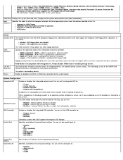
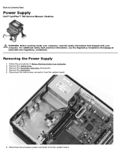
Remove the hard drive. 5. Disconnect the processor power connector from the system board. 6. For additional safety best practices information, see the Regulatory Compliance Homepage at www.dell.com/regulatory_compliance. Remove the optical drive. 3. Remove the secondary hard drive (if present). 4. ...Removing the Power Supply 1. Disconnect the main power connector from the system board. Back to Contents Page Power Supply Dell™ OptiPlex™ 780 Service Manual-Desktop WARNING: Before working inside your computer, read the safety information that shipped with your computer. ...
Remove the hard drive. 5. Disconnect the processor power connector from the system board. 6. For additional safety best practices information, see the Regulatory Compliance Homepage at www.dell.com/regulatory_compliance. Remove the optical drive. 3. Remove the secondary hard drive (if present). 4. ...Removing the Power Supply 1. Disconnect the main power connector from the system board. Back to Contents Page Power Supply Dell™ OptiPlex™ 780 Service Manual-Desktop WARNING: Before working inside your computer, read the safety information that shipped with your computer. ...

Service Manual
Page 37
Release the processor power connector cable from routing guides under the system board. 7.
Release the processor power connector cable from routing guides under the system board. 7.

Service Manual
Page 45
Follow the procedures in Before Working Inside Your Computer. 2. Remove the riser cage. 3. Disconnect the floppy-drive data cable from the system board. Remove the memory. 5. Removing the System Board 1. Back to Contents Page System Board Dell™ OptiPlex™ 780 Service Manual-Desktop WARNING: Before working inside your computer, read the safety information that shipped with your computer. For additional safety best practices information, see the Regulatory Compliance Homepage at www.dell.com/regulatory_compliance. Remove the heat sink and processor. 4.
Follow the procedures in Before Working Inside Your Computer. 2. Remove the riser cage. 3. Disconnect the floppy-drive data cable from the system board. Remove the memory. 5. Removing the System Board 1. Back to Contents Page System Board Dell™ OptiPlex™ 780 Service Manual-Desktop WARNING: Before working inside your computer, read the safety information that shipped with your computer. For additional safety best practices information, see the Regulatory Compliance Homepage at www.dell.com/regulatory_compliance. Remove the heat sink and processor. 4.

Service Manual
Page 50
11. Disconnect the processor power cable.
11. Disconnect the processor power cable.
Service Manual
Page 70
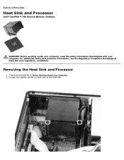
Follow the procedures in Before Working Inside Your Computer. 2. For additional safety best practices information, see the Regulatory Compliance Homepage at www.dell.com/regulatory_compliance. Loosen the captive screws on each side of the heat sink. Removing the Heat Sink and Processor 1. Back to Contents Page Heat Sink and Processor Dell™ OptiPlex™ 780 Service Manual-Desktop WARNING: Before working inside your computer, read the safety information that shipped with your computer.
Follow the procedures in Before Working Inside Your Computer. 2. For additional safety best practices information, see the Regulatory Compliance Homepage at www.dell.com/regulatory_compliance. Loosen the captive screws on each side of the heat sink. Removing the Heat Sink and Processor 1. Back to Contents Page Heat Sink and Processor Dell™ OptiPlex™ 780 Service Manual-Desktop WARNING: Before working inside your computer, read the safety information that shipped with your computer.

Service Manual
Page 72
Open the processor cover by sliding the release lever from under the cover latch on the socket. 5. Then, pull the lever back to release the processor cover.
Open the processor cover by sliding the release lever from under the cover latch on the socket. 5. Then, pull the lever back to release the processor cover.

Service Manual
Page 73
6. Lift the processor cover.
6. Lift the processor cover.

Service Manual
Page 74
7. Remove the processor from the computer.
7. Remove the processor from the computer.

Service Manual
Page 75
Back to fall on the pins in reverse order. Replacing the Heat Sink and Processor To replace the heat sink and processor, perform the above steps in the socket. CAUTION: When replacing the processor, do not touch any of the pins inside the socket or allow any objects to Contents Page
Back to fall on the pins in reverse order. Replacing the Heat Sink and Processor To replace the heat sink and processor, perform the above steps in the socket. CAUTION: When replacing the processor, do not touch any of the pins inside the socket or allow any objects to Contents Page

Technical Guide
Page 2
... (MT) View Desktop Computer (DT) View Small Form Factor Computer (SFF) View Ultra Small Form Factor Computer (USFF) View MARKETING SYSTEM CONFIGURATIONS Operating System, Chipset Processor Advanced System Manageability Modes, Memory Drives and Removable Storage, System Board Connectors Graphics/Video Controller External Ports/Connectors Communications-Network Adapter (NIC), Modem Audio and...
... (MT) View Desktop Computer (DT) View Small Form Factor Computer (SFF) View Ultra Small Form Factor Computer (USFF) View MARKETING SYSTEM CONFIGURATIONS Operating System, Chipset Processor Advanced System Manageability Modes, Memory Drives and Removable Storage, System Board Connectors Graphics/Video Controller External Ports/Connectors Communications-Network Adapter (NIC), Modem Audio and...


