Setup and Features Information Tech Sheet (Desktop, Mini-Tower, Small Form Factor)
Page 8
... lights located on state; Drives (continued) Internally accessible: 3.5-inch SATA drive bays Available devices: 2.5-inch SATA hard drive (with the system board. one (slimline drive) Control Lights and Diagnostic ...Dell Support website at support.dell.com/manuals. two Desktop - two Desktop and Small Form Factor - one Mini-Tower and Desktop - two Mini-Tower - one Mini-Tower, Desktop, and Small Form Factor - Amber light - Drive activity light Green light - Blinking green light indicates that the computer is not detecting a physical connection to the hard drive...
... lights located on state; Drives (continued) Internally accessible: 3.5-inch SATA drive bays Available devices: 2.5-inch SATA hard drive (with the system board. one (slimline drive) Control Lights and Diagnostic ...Dell Support website at support.dell.com/manuals. two Desktop - two Desktop and Small Form Factor - one Mini-Tower and Desktop - two Mini-Tower - one Mini-Tower, Desktop, and Small Form Factor - Amber light - Drive activity light Green light - Blinking green light indicates that the computer is not detecting a physical connection to the hard drive...
Setup and Features Information Tech Sheet (Ultra Small Form Factor)
Page 5
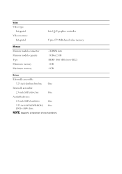
Video Video type: Integrated Video memory: Integrated Intel Q45 graphics controller Upto 1759 MB shared video memory Memory Memory module connector Memory module capacity Type Minimum memory Maximum memory 2 DIMM slots 1 GB or 2 GB DDR3 1066 MHz (non-ECC) 1 GB 4 GB Drives Externally accessible: 5.25-inch slimline drive bay One Internally accessible: 2.5-inch SATA drive bay One Available devices: 2.5-inch SATA hard drive One 5.25-inch SATA DVD-ROM, One DVD+/-RW drive NOTE: Supports a maximum of one hard drive.
Video Video type: Integrated Video memory: Integrated Intel Q45 graphics controller Upto 1759 MB shared video memory Memory Memory module connector Memory module capacity Type Minimum memory Maximum memory 2 DIMM slots 1 GB or 2 GB DDR3 1066 MHz (non-ECC) 1 GB 4 GB Drives Externally accessible: 5.25-inch slimline drive bay One Internally accessible: 2.5-inch SATA drive bay One Available devices: 2.5-inch SATA hard drive One 5.25-inch SATA DVD-ROM, One DVD+/-RW drive NOTE: Supports a maximum of one hard drive.
Setup and Features Information Tech Sheet (Ultra Small Form Factor)
Page 6
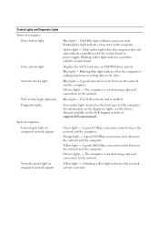
...light) - A blinking yellow light indicates that the computer is not detecting a physical connection to the network. Displays the SATA hard drive or CD/DVD drive activity. Blue light - The computer is present. A good 10 Mbps connection exists between the network and the computer. Solid blue... the Dell Support website at support.dell.com/manuals. Blinking amber light indicates a problem with the system board or power supply. Green light - The WiFi network card is enabled. Control Lights and Diagnostic Lights Front of computer: Power button light Drive activity ...
...light) - A blinking yellow light indicates that the computer is not detecting a physical connection to the network. Displays the SATA hard drive or CD/DVD drive activity. Blue light - The computer is present. A good 10 Mbps connection exists between the network and the computer. Solid blue... the Dell Support website at support.dell.com/manuals. Blinking amber light indicates a problem with the system board or power supply. Green light - The WiFi network card is enabled. Control Lights and Diagnostic Lights Front of computer: Power button light Drive activity ...
Service Manual
Page 5
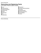
Back to Contents Page Removing and Replacing Parts Dell™ OptiPlex™ 780 Service Manual-Desktop Cover Primary Hard Drive Floppy Drive (Optional) Expansion Card Memory Power Supply Fan System Board Optical Drive Secondary Hard Drive (Optional) Riser Cage Standard Back Plate Heat Sink and Processor Coin-Cell Battery IO Panel Back to Contents Page
Back to Contents Page Removing and Replacing Parts Dell™ OptiPlex™ 780 Service Manual-Desktop Cover Primary Hard Drive Floppy Drive (Optional) Expansion Card Memory Power Supply Fan System Board Optical Drive Secondary Hard Drive (Optional) Riser Cage Standard Back Plate Heat Sink and Processor Coin-Cell Battery IO Panel Back to Contents Page
Service Manual
Page 8
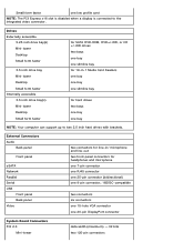
...(s) Mini-tower Desktop Small form factor for SATA DVD-ROM, DVD+/-RW, or CD +/-RW drives two bays one bay one slimline bay for 19-in / microphone and line-out two front-panel connectors for hard drives two bays one bay one low profile card NOTE: The PCI Express x16 slot is disabled... when a display is connected to two 2.5 inch hard drives with brackets. External Connectors Audio Back panel Front panel eSATA Network Parallel Serial USB Front panel Back panel Video two connectors for line-in -1 Media ...
...(s) Mini-tower Desktop Small form factor for SATA DVD-ROM, DVD+/-RW, or CD +/-RW drives two bays one bay one slimline bay for 19-in / microphone and line-out two front-panel connectors for hard drives two bays one bay one low profile card NOTE: The PCI Express x16 slot is disabled... when a display is connected to two 2.5 inch hard drives with brackets. External Connectors Audio Back panel Front panel eSATA Network Parallel Serial USB Front panel Back panel Video two connectors for line-in -1 Media ...
Service Manual
Page 9
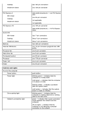
...Mini-tower Desktop Small form factor Memory Internal USB device Processor fan Hard-drive fan Front panel control Processor Power 12V Power Controls and Lights Front of the computer Power button Power light Drive activity light Network connectivity light two 120-pin connectors one 24-pin... connector push button blinking green - indicates that the system board is unable to the hard drive green - indicates that the computer is not detecting a physical connection to the network indicates that the computer is in sleep state solid...
...Mini-tower Desktop Small form factor Memory Internal USB device Processor fan Hard-drive fan Front panel control Processor Power 12V Power Controls and Lights Front of the computer Power button Power light Drive activity light Network connectivity light two 120-pin connectors one 24-pin... connector push button blinking green - indicates that the system board is unable to the hard drive green - indicates that the computer is not detecting a physical connection to the network indicates that the computer is in sleep state solid...
Service Manual
Page 12
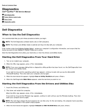
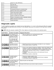
... only on (or restart) your computer and try again. Start the Dell Diagnostics from either your hard drive or from your computer and try again. 3. Starting the Dell Diagnostics From Your Hard Drive 1. On the next startup, the computer boots according to the devices .... When the DELL logo appears, press immediately. When the DELL logo appears, press immediately. Back to Contents Page Diagnostics Dell™ OptiPlex™ 780 Service Manual Dell Diagnostics Power Button Light Codes Beep Codes Diagnostic Lights Dell Diagnostics When to Use the Dell Diagnostics It is...
... only on (or restart) your computer and try again. Start the Dell Diagnostics from either your hard drive or from your computer and try again. 3. Starting the Dell Diagnostics From Your Hard Drive 1. On the next startup, the computer boots according to the devices .... When the DELL logo appears, press immediately. When the DELL logo appears, press immediately. Back to Contents Page Diagnostics Dell™ OptiPlex™ 780 Service Manual Dell Diagnostics Power Button Light Codes Beep Codes Diagnostic Lights Dell Diagnostics When to Use the Dell Diagnostics It is...

Service Manual
Page 14
If the Hard Drive light is off , light is blank. Look at the diagnostic lights for further information. The BIOS will turn the light to this state to be ... Green System is in. Most beep codes indicate a fatal error that the power supply needs to indicate it has started fetching op-codes. If the Hard Drive light on, it is fine. Second state of light at power up . Indicates the POWER_GOOD signal is active and it is probable that the power...
If the Hard Drive light is off , light is blank. Look at the diagnostic lights for further information. The BIOS will turn the light to this state to be ... Green System is in. Most beep codes indicate a fatal error that the power supply needs to indicate it has started fetching op-codes. If the Hard Drive light on, it is fine. Second state of light at power up . Indicates the POWER_GOOD signal is active and it is probable that the power...
Service Manual
Page 15
... Serial or parallel port test failure Failure to decompress code to identify the problem. If the problem persists, contact Dell. A possible floppy drive or hard drive failure has occurred. If the problem persists, contact Dell . If the problem persists, contact Dell. If the computer starts normally, continue to the operating system. If the problem persists, contact...
... Serial or parallel port test failure Failure to decompress code to identify the problem. If the problem persists, contact Dell. A possible floppy drive or hard drive failure has occurred. If the problem persists, contact Dell . If the problem persists, contact Dell. If the computer starts normally, continue to the operating system. If the problem persists, contact...

Service Manual
Page 16
...it is correct for the devices installed on the screen identifying a problem with a device (such as the floppy drive or hard drive), check the device to the system board . If the operating system is attempting to boot from the computer for ...each expansion card installed. Ensure that all modules without error. If the problem persists, contact Dell. Repeat this process for resource conflicts. If the problem persists, contact Dell...
...it is correct for the devices installed on the screen identifying a problem with a device (such as the floppy drive or hard drive), check the device to the system board . If the operating system is attempting to boot from the computer for ...each expansion card installed. Ensure that all modules without error. If the problem persists, contact Dell. Repeat this process for resource conflicts. If the problem persists, contact Dell...
Service Manual
Page 18
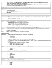
... option is disable Enable - This field enable and disable the internal USB for Flex Bay is part of the integrated hard drive controller. Processor information: Displays the Processor Type, Processor Speed, Processor Bus Speed, Processor L2 cache, Processor ID, Microcode Version, Multi ...with USB support will affect floppy operation. You can set the USB controller to : Disable Auto (default) COM1 COM3 This field controls whether hard drive errors for Flex Bay is disabled by default. You can set the serial port to : Enable (default) Disable No boot Operating systems ...
... option is disable Enable - This field enable and disable the internal USB for Flex Bay is part of the integrated hard drive controller. Processor information: Displays the Processor Type, Processor Speed, Processor Bus Speed, Processor L2 cache, Processor ID, Microcode Version, Multi ...with USB support will affect floppy operation. You can set the USB controller to : Disable Auto (default) COM1 COM3 This field controls whether hard drive errors for Flex Bay is disabled by default. You can set the serial port to : Enable (default) Disable No boot Operating systems ...

Service Manual
Page 19
... restricted access to the computer's system setup program in multiple performance states. This option is allowed to optimize your hard drives performance and acoustic noise level based on your personal preferences. Enables or disables the trusted platform module (TPM) security... A PCI Express Graphic(PEG) card will improve with the System Password option. Trusted Execution Enable Intel® Virtualization Technology for older drives) Quiet- Serial Port #2 Miscellaneous Devices The Operating System may optionally use this feature. Auto(default) - When disabled, the system ...
... restricted access to the computer's system setup program in multiple performance states. This option is allowed to optimize your hard drives performance and acoustic noise level based on your personal preferences. Enables or disables the trusted platform module (TPM) security... A PCI Express Graphic(PEG) card will improve with the System Password option. Trusted Execution Enable Intel® Virtualization Technology for older drives) Quiet- Serial Port #2 Miscellaneous Devices The Operating System may optionally use this feature. Auto(default) - When disabled, the system ...

Service Manual
Page 20
...be able to disabled. This option is disabled by default. Image Server Lookup Method ImageServer IP Specifies how the ImageServer looks for the hard drive connected to set by default. Enables or disables the execute disable mode of the system fan. You can set by default. Specifies ...NOTE: You must set the Integrated NIC to your computer. Maintenance Service Tag Asset Tag SERR Messages Displays the Service Tag of the hard drives connected to Enable with which the client software communicates. This option is enabled by typing the values in the system setup. This ...
...be able to disabled. This option is disabled by default. Image Server Lookup Method ImageServer IP Specifies how the ImageServer looks for the hard drive connected to set by default. Enables or disables the execute disable mode of the system fan. You can set by default. Specifies ...NOTE: You must set the Integrated NIC to your computer. Maintenance Service Tag Asset Tag SERR Messages Displays the Service Tag of the hard drives connected to Enable with which the client software communicates. This option is enabled by typing the values in the system setup. This ...
Service Manual
Page 24
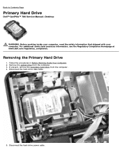
Back to Contents Page Primary Hard Drive Dell™ OptiPlex™ 780 Service Manual-Desktop WARNING: Before working inside your computer, read the safety information that shipped with your computer. Disconnect the hard-drive data cable. 5. For additional safety best practices information, see the Regulatory Compliance Homepage at www.dell.com/regulatory_compliance. Follow the procedures in Before Working Inside...
Back to Contents Page Primary Hard Drive Dell™ OptiPlex™ 780 Service Manual-Desktop WARNING: Before working inside your computer, read the safety information that shipped with your computer. Disconnect the hard-drive data cable. 5. For additional safety best practices information, see the Regulatory Compliance Homepage at www.dell.com/regulatory_compliance. Follow the procedures in Before Working Inside...

Service Manual
Page 26
7. Lift the hard drive and remove it from the system.
7. Lift the hard drive and remove it from the system.

Service Manual
Page 27
Back to Contents Page Replacing the Primary Hard Drive To replace the hard drive, perform the above steps in reverse order.
Back to Contents Page Replacing the Primary Hard Drive To replace the hard drive, perform the above steps in reverse order.
Service Manual
Page 36
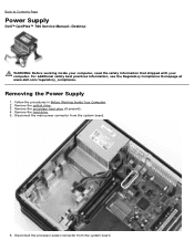
For additional safety best practices information, see the Regulatory Compliance Homepage at www.dell.com/regulatory_compliance. Remove the secondary hard drive (if present). 4. Remove the hard drive. 5. Disconnect the processor power connector from the system board. 6. Back to Contents Page Power Supply Dell™ OptiPlex™ 780 Service Manual-Desktop WARNING: Before working inside your computer, read the safety...
For additional safety best practices information, see the Regulatory Compliance Homepage at www.dell.com/regulatory_compliance. Remove the secondary hard drive (if present). 4. Remove the hard drive. 5. Disconnect the processor power connector from the system board. 6. Back to Contents Page Power Supply Dell™ OptiPlex™ 780 Service Manual-Desktop WARNING: Before working inside your computer, read the safety...
Service Manual
Page 49
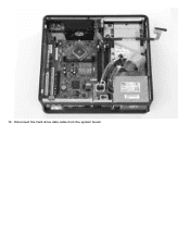
10. Disconnect the hard-drive data cable from the system board.
10. Disconnect the hard-drive data cable from the system board.
Service Manual
Page 59
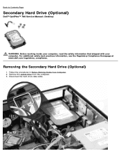
For additional safety best practices information, see the Regulatory Compliance Homepage at www.dell.com/regulatory_compliance. Disconnect the hard-drive data cable. Remove the optical drive from the computer. 3. Follow the procedures in Before Working Inside Your Computer. 2. Removing the Secondary Hard Drive (Optional) 1. Back to Contents Page Secondary Hard Drive (Optional) Dell™ OptiPlex™ 780 Service Manual-Desktop WARNING: Before working inside your computer, read the safety information that shipped with your computer.
For additional safety best practices information, see the Regulatory Compliance Homepage at www.dell.com/regulatory_compliance. Disconnect the hard-drive data cable. Remove the optical drive from the computer. 3. Follow the procedures in Before Working Inside Your Computer. 2. Removing the Secondary Hard Drive (Optional) 1. Back to Contents Page Secondary Hard Drive (Optional) Dell™ OptiPlex™ 780 Service Manual-Desktop WARNING: Before working inside your computer, read the safety information that shipped with your computer.
Service Manual
Page 60
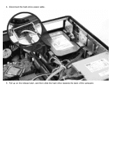
4. Pull up on the release latch, and then slide the hard drive towards the back of the computer. Disconnect the hard-drive power cable. 5.
4. Pull up on the release latch, and then slide the hard drive towards the back of the computer. Disconnect the hard-drive power cable. 5.


