
Quick Reference Guide
Page 3
Contents Finding Information 5 Setting Up Your Computer 10 Set Up Your Keyboard and Mouse 11 Set Up Your Monitor 12 Power Connections 12 Before You Begin 13 Recommended Tools 13 Turning Off Your Computer 13 Before Working Inside Your Computer 14 Mini Tower Computer 16 System ...
Contents Finding Information 5 Setting Up Your Computer 10 Set Up Your Keyboard and Mouse 11 Set Up Your Monitor 12 Power Connections 12 Before You Begin 13 Recommended Tools 13 Turning Off Your Computer 13 Before Working Inside Your Computer 14 Mini Tower Computer 16 System ...
Quick Reference Guide
Page 11
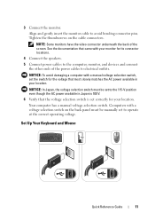
...-selection switch, set to operate at the correct operating voltage. NOTE: Some monitors have the video connector underneath the back of the power cables to avoid bending connector pins. Your computer has a manual voltage-selection switch. Set Up Your Keyboard and Mouse Quick Reference Guide...on the cable connectors. See the documentation that the voltage selection switch is set to the 115-V position even though the AC power available in your location. Tighten the thumbscrews on the back panel must be manually set correctly for its connector locations. 4 Connect the ...
...-selection switch, set to operate at the correct operating voltage. NOTE: Some monitors have the video connector underneath the back of the power cables to avoid bending connector pins. Your computer has a manual voltage-selection switch. Set Up Your Keyboard and Mouse Quick Reference Guide...on the cable connectors. See the documentation that the voltage selection switch is set to the 115-V position even though the AC power available in your location. Tighten the thumbscrews on the back panel must be manually set correctly for its connector locations. 4 Connect the ...
Quick Reference Guide
Page 14
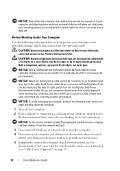
...; Some cables have a connector with care. See the documentation that came with your computer. 2 If the computer is not covered by Dell is connected to a docking device (docked), undock it from the network wall jack. 3 Disconnect all attached devices are turned off . CAUTION... ensure that the computer and all telephone or network cables from the computer. 4 Disconnect your operating system, press and hold the power button for instructions. NOTICE: To avoid damaging the computer, perform the following safety guidelines to help protect your computer from their electrical ...
...; Some cables have a connector with care. See the documentation that came with your computer. 2 If the computer is not covered by Dell is connected to a docking device (docked), undock it from the network wall jack. 3 Disconnect all attached devices are turned off . CAUTION... ensure that the computer and all telephone or network cables from the computer. 4 Disconnect your operating system, press and hold the power button for instructions. NOTICE: To avoid damaging the computer, perform the following safety guidelines to help protect your computer from their electrical ...
Quick Reference Guide
Page 17
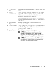
...connected, such as joysticks or cameras, or for bootable USB devices (see "Diagnostic Lights" on page 66. 7 power button Press this button to turn off the computer by pressing the power button. See "Turning Off Your Computer" on page 13 for more information on booting to a USB device). NOTICE:... If your online User's Guide for more information, see your operating system has ACPI enabled, when you press the power button the computer will perform...
...connected, such as joysticks or cameras, or for bootable USB devices (see "Diagnostic Lights" on page 66. 7 power button Press this button to turn off the computer by pressing the power button. See "Turning Off Your Computer" on page 13 for more information on booting to a USB device). NOTICE:... If your online User's Guide for more information, see your operating system has ACPI enabled, when you press the power button the computer will perform...
Quick Reference Guide
Page 18
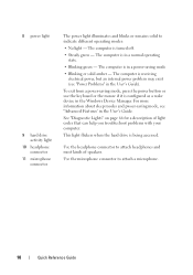
.... • Steady green - See "Diagnostic Lights" on page 66 for a description of speakers. The computer is receiving electrical power, but an internal power problem may exist (see "Advanced Features' in the User's Guide. Use the headphone connector to attach headphones and most kinds of... help you troubleshoot problems with your computer. The computer is in the User's Guide). 8 power light 9 hard drive activity light 10 headphone connector 11 microphone connector The power light illuminates and blinks or remains solid to attach a microphone. 18 Quick Reference Guide The ...
.... • Steady green - See "Diagnostic Lights" on page 66 for a description of speakers. The computer is receiving electrical power, but an internal power problem may exist (see "Advanced Features' in the User's Guide. Use the headphone connector to attach headphones and most kinds of... help you troubleshoot problems with your computer. The computer is in the User's Guide). 8 power light 9 hard drive activity light 10 headphone connector 11 microphone connector The power light illuminates and blinks or remains solid to attach a microphone. 18 Quick Reference Guide The ...

Quick Reference Guide
Page 20
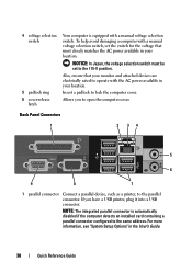
... with a manual voltage-selection switch, set to the 115-V position. Also, ensure that most closely matches the AC power available in your location. 4 power connector Insert the power cable. 5 back panel connectors Plug serial, USB, and other devices into a USB connector. NOTE: The integrated parallel... connector is equipped with the AC power available in your monitor and attached devices are electrically rated to operate with a manual voltage-selection switch switch. NOTICE: In ...
... with a manual voltage-selection switch, set to the 115-V position. Also, ensure that most closely matches the AC power available in your location. 4 power connector Insert the power cable. 5 back panel connectors Plug serial, USB, and other devices into a USB connector. NOTE: The integrated parallel... connector is equipped with the AC power available in your monitor and attached devices are electrically rated to operate with a manual voltage-selection switch switch. NOTICE: In ...
Quick Reference Guide
Page 24
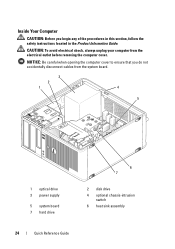
..., follow the safety instructions located in the Product Information Guide. CAUTION: To avoid electrical shock, always unplug your computer from the system board. 3 2 1 4 5 1 optical drive 3 power supply 5 system board 7 hard drive 6 7 2 disk drive 4 optional chassis-intrusion switch 6 heat sink assembly 24 Quick Reference Guide Inside Your Computer CAUTION: Before you do...
..., follow the safety instructions located in the Product Information Guide. CAUTION: To avoid electrical shock, always unplug your computer from the system board. 3 2 1 4 5 1 optical drive 3 power supply 5 system board 7 hard drive 6 7 2 disk drive 4 optional chassis-intrusion switch 6 heat sink assembly 24 Quick Reference Guide Inside Your Computer CAUTION: Before you do...
Quick Reference Guide
Page 26
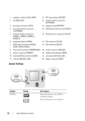
... reset jumper (RTCRST) 2 fan (FAN_CPU) 13 intrusion switch connector (INTRUDER) 3 processor connector (CPU) 14 battery socket (BATTERY) 4 processor power connector (12VPOWER) 15 PCI Express x16 connector (SLOT1) 5 memory module connectors (DIMM_1, DIMM_2, DIMM_3, DIMM_4) 16 PCI Express x1 connector (SLOT4... connector (SLOT3) 8 front-panel connector (FRONTPANEL) 19 serial connector (SERIAL2) 9 power connector (POWER) 20 system board speaker (BEEP) 10 external SATA connector (eSATA) 21 aux power LED (AUX_LED) 11 internal USB (INT_USB) 22 floppy connector (DSKT) Jumper Settings ...
... reset jumper (RTCRST) 2 fan (FAN_CPU) 13 intrusion switch connector (INTRUDER) 3 processor connector (CPU) 14 battery socket (BATTERY) 4 processor power connector (12VPOWER) 15 PCI Express x16 connector (SLOT1) 5 memory module connectors (DIMM_1, DIMM_2, DIMM_3, DIMM_4) 16 PCI Express x1 connector (SLOT4... connector (SLOT3) 8 front-panel connector (FRONTPANEL) 19 serial connector (SERIAL2) 9 power connector (POWER) 20 system board speaker (BEEP) 10 external SATA connector (eSATA) 21 aux power LED (AUX_LED) 11 internal USB (INT_USB) 22 floppy connector (DSKT) Jumper Settings ...
Quick Reference Guide
Page 28
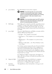
NOTICE: If your operating system has ACPI enabled, when you press the power button the computer will perform an operating system shutdown. 4 Dell badge This badge can be rotated to match the orientation of your computer. 6 diagnostic lights Use the lights to help you ...troubleshoot a computer problem based on the computer. To rotate, place fingers around the outside of the badge. 5 power light The power light illuminates and ...
NOTICE: If your operating system has ACPI enabled, when you press the power button the computer will perform an operating system shutdown. 4 Dell badge This badge can be rotated to match the orientation of your computer. 6 diagnostic lights Use the lights to help you ...troubleshoot a computer problem based on the computer. To rotate, place fingers around the outside of the badge. 5 power light The power light illuminates and ...
Quick Reference Guide
Page 29
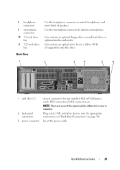
...supported) into the appropriate connectors (see "Back Panel Connectors" on page 30). NOTE: The back view of speakers. Insert the power cable. Use the microphone connector to attach headphones and most kinds of the system will be different if a riser is installed....an optical drive. Plug serial, USB, and other devices into this drive. 1 2 3 4 5 6 1 card slots (3) 2 back panel connectors 3 power connector Access connectors for any installed PCI or PCI Express cards, PS/2 connector, eSATA connector, etc. Quick Reference Guide 29 8 headphone connector 9 microphone connector...
...supported) into the appropriate connectors (see "Back Panel Connectors" on page 30). NOTE: The back view of speakers. Insert the power cable. Use the microphone connector to attach headphones and most kinds of the system will be different if a riser is installed....an optical drive. Plug serial, USB, and other devices into this drive. 1 2 3 4 5 6 1 card slots (3) 2 back panel connectors 3 power connector Access connectors for any installed PCI or PCI Express cards, PS/2 connector, eSATA connector, etc. Quick Reference Guide 29 8 headphone connector 9 microphone connector...
Quick Reference Guide
Page 30
... rated to the parallel connector. NOTE: The integrated parallel connector is equipped with a manual voltage selection switch. Also, ensure that most closely matches the AC power available in your location. Back Panel Connectors 1 2 34 5 6 9 8 7 1 parallel connector Connect a parallel device, such as a printer, to operate with a manual voltage selection switch, ... Insert a padlock to the 115-V position. Allows you have a USB printer, plug it into a USB connector. To help avoid damaging a computer with the AC power available in the User's Guide. 30 Quick Reference Guide
... rated to the parallel connector. NOTE: The integrated parallel connector is equipped with a manual voltage selection switch. Also, ensure that most closely matches the AC power available in your location. Back Panel Connectors 1 2 34 5 6 9 8 7 1 parallel connector Connect a parallel device, such as a printer, to operate with a manual voltage selection switch, ... Insert a padlock to the 115-V position. Allows you have a USB printer, plug it into a USB connector. To help avoid damaging a computer with the AC power available in the User's Guide. 30 Quick Reference Guide
Quick Reference Guide
Page 34
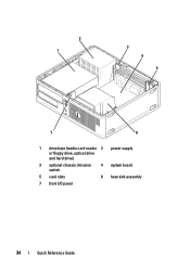
2 1 3 4 5 7 6 1 drive bays (media card reader 2 power supply or floppy drive, optical drive and hard drive) 3 optional chassis-intrusion switch 4 system board 5 card slots 6 heat sink assembly 7 front I/O panel 34 Quick Reference Guide
2 1 3 4 5 7 6 1 drive bays (media card reader 2 power supply or floppy drive, optical drive and hard drive) 3 optional chassis-intrusion switch 4 system board 5 card slots 6 heat sink assembly 7 front I/O panel 34 Quick Reference Guide
Quick Reference Guide
Page 38
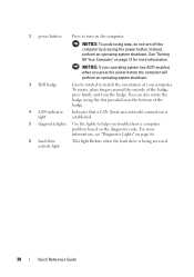
2 power button Press to match the orientation of your operating system has ACPI enabled, when you troubleshoot a computer problem based on the diagnostic code. NOTICE: To ... light flickers when the hard drive is established. 5 diagnostic lights Use the lights to help you press the power button the computer will perform an operating system shutdown. 3 Dell badge Can be rotated to turn off the computer by pressing the power button. NOTICE: If your computer. Instead, perform an operating system shutdown.
2 power button Press to match the orientation of your operating system has ACPI enabled, when you troubleshoot a computer problem based on the diagnostic code. NOTICE: To ... light flickers when the hard drive is established. 5 diagnostic lights Use the lights to help you press the power button the computer will perform an operating system shutdown. 3 Dell badge Can be rotated to turn off the computer by pressing the power button. NOTICE: If your computer. Instead, perform an operating system shutdown.
Quick Reference Guide
Page 39
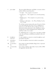
...as a wake device in the User's Guide. For more information about sleep modes and exiting from a power-saving mode, press the power button or use the keyboard or the mouse if it is in the User's Guide. 7 power light 8 headphone connector 9 microphone connector 10 3.5-inch drive bay 11 5.25-inch drive bay The... can help you troubleshoot problems with your computer. Can contain an optional slimline floppy drive or optional media card reader. Quick Reference Guide 39 See "Dell Diagnostics" on page 61 for Windows XP and Vista" in a power-saving mode. • Blinking or solid amber -
...as a wake device in the User's Guide. For more information about sleep modes and exiting from a power-saving mode, press the power button or use the keyboard or the mouse if it is in the User's Guide. 7 power light 8 headphone connector 9 microphone connector 10 3.5-inch drive bay 11 5.25-inch drive bay The... can help you troubleshoot problems with your computer. Can contain an optional slimline floppy drive or optional media card reader. Quick Reference Guide 39 See "Dell Diagnostics" on page 61 for Windows XP and Vista" in a power-saving mode. • Blinking or solid amber -

Quick Reference Guide
Page 40
... voltage selection switch, set to the 115-V position. Your computer is equipped with the AC power available in your location. Also, ensure that most closely matches the AC power available in your location. Insert a padlock to open the computer cover. 40 Quick Reference Guide... Insert the power cable. Back View 1 2 3 4 5 6 1 card slots (2) 2 back panel connectors 3 power connector 4 voltage selection switch 5 padlock ring 6 cover release latch Access connectors for the voltage that...
... voltage selection switch, set to the 115-V position. Your computer is equipped with the AC power available in your location. Also, ensure that most closely matches the AC power available in your location. Insert a padlock to open the computer cover. 40 Quick Reference Guide... Insert the power cable. Back View 1 2 3 4 5 6 1 card slots (2) 2 back panel connectors 3 power connector 4 voltage selection switch 5 padlock ring 6 cover release latch Access connectors for the voltage that...
Quick Reference Guide
Page 45
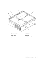
3 4 2 1 1 drive-release latch 3 power supply 5 system board 5 6 2 optical drive 4 hard drive 6 heat sink assembly Quick Reference Guide 45
3 4 2 1 1 drive-release latch 3 power supply 5 system board 5 6 2 optical drive 4 hard drive 6 heat sink assembly Quick Reference Guide 45
Quick Reference Guide
Page 47
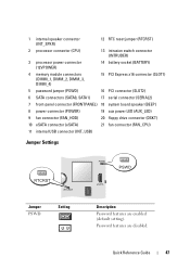
... speaker connector (INT_SPKR) 12 RTC reset jumper (RTCRST) 2 processor connector (CPU) 13 intrusion switch connector (INTRUDER) 3 processor power connector (12VPOWER) 14 battery socket (BATTERY) 4 memory module connectors (DIMM_1, DIMM_2, DIMM_3, DIMM_4) 15 PCI Express x16 connector... SATA connectors (SATA0, SATA1) 17 serial connector (SERIAL2) 7 front-panel connector (FRONTPANEL) 18 system board speaker (BEEP) 8 power connector (POWER) 19 aux power LED (AUX_LED) 9 fan connector (FAN_HDD) 20 floppy drive connector (DSKT) 10 eSATA connector (eSATA) 21 fan connector (FAN_CPU)...
... speaker connector (INT_SPKR) 12 RTC reset jumper (RTCRST) 2 processor connector (CPU) 13 intrusion switch connector (INTRUDER) 3 processor power connector (12VPOWER) 14 battery socket (BATTERY) 4 memory module connectors (DIMM_1, DIMM_2, DIMM_3, DIMM_4) 15 PCI Express x16 connector... SATA connectors (SATA0, SATA1) 17 serial connector (SERIAL2) 7 front-panel connector (FRONTPANEL) 18 system board speaker (BEEP) 8 power connector (POWER) 19 aux power LED (AUX_LED) 9 fan connector (FAN_HDD) 20 floppy drive connector (DSKT) 10 eSATA connector (eSATA) 21 fan connector (FAN_CPU)...
Quick Reference Guide
Page 49
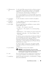
...Setup" in a normal operating state. • Blinking green - Install a D-module optical drive, second hard drive, or floppy drive in a power-saving mode. • Blinking or solid yellow - Use the microphone connector to indicate different states: • No light - Use the headphone connector.... NOTICE: To avoid losing data, do not block these cooling vents. 1 USB connectors (2) 2 microphone connector 3 headphone connector 4 power light 5 power button 6 vents 7 module bay Use the front USB connectors for devices that you connect occasionally, such as joysticks or cameras, or ...
...Setup" in a normal operating state. • Blinking green - Install a D-module optical drive, second hard drive, or floppy drive in a power-saving mode. • Blinking or solid yellow - Use the microphone connector to indicate different states: • No light - Use the headphone connector.... NOTICE: To avoid losing data, do not block these cooling vents. 1 USB connectors (2) 2 microphone connector 3 headphone connector 4 power light 5 power button 6 vents 7 module bay Use the front USB connectors for devices that you connect occasionally, such as joysticks or cameras, or ...
Quick Reference Guide
Page 51
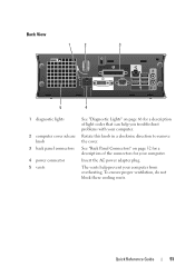
Insert the AC power adapter plug. Quick Reference Guide 51 Rotate this knob in a clockwise direction to remove the cover. To ensure proper ventilation, do not block these cooling ... problems with your computer. See "Back Panel Connectors" on page 66 for your computer. Back View 1 2 3 5 4 1 diagnostic lights 2 computer cover release knob 3 back panel connectors 4 power connector 5 vents See "Diagnostic Lights" on page 52 for a description of the connectors for a description of light codes that can help prevent your computer from...
Insert the AC power adapter plug. Quick Reference Guide 51 Rotate this knob in a clockwise direction to remove the cover. To ensure proper ventilation, do not block these cooling ... problems with your computer. See "Back Panel Connectors" on page 66 for your computer. Back View 1 2 3 5 4 1 diagnostic lights 2 computer cover release knob 3 back panel connectors 4 power connector 5 vents See "Diagnostic Lights" on page 52 for a description of the connectors for a description of light codes that can help prevent your computer from...
Quick Reference Guide
Page 53
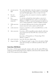
... receiving network data. Quick Reference Guide 53 Connecting a VGA Monitor If you have a VGA monitor, see "Connecting a VGA Monitor" on page 53. 10 power connector Insert the AC power adapter plug. 11 diagnostic lights See "Diagnostic Lights" on page 66 for a description of your computer, and connect the monitor cable to the...
... receiving network data. Quick Reference Guide 53 Connecting a VGA Monitor If you have a VGA monitor, see "Connecting a VGA Monitor" on page 53. 10 power connector Insert the AC power adapter plug. 11 diagnostic lights See "Diagnostic Lights" on page 66 for a description of your computer, and connect the monitor cable to the...


