
Dell OptiPlex 755 Support Question
Dell OptiPlex 755 Support Question
Find answers below for this question about Dell OptiPlex 755.Need a Dell OptiPlex 755 manual? We have 3 online manuals for this item!
Question posted by gkiggch on January 2nd, 2014
How To Wire Up Dell Optiplex 755 Power Supply
The person who posted this question about this Dell product did not include a detailed explanation. Please use the "Request More Information" button to the right if more details would help you to answer this question.
Current Answers
Answer #1: Posted by prateekk007 on January 3rd, 2014 5:11 AM
prateekk007

Member since:
December 5th, 2012 Points: 2,137,520

Member since:
December 5th, 2012 Points: 2,137,520
Hi gkiggch,
Please click on the link given below to get the instructions for removing/reinstalling the Powers supply. I would recommend you to consult a local technician for professional helps so that any damage of the device can be avoided.
Please reply if you have further queries.
To know more about Dell Product Support, Drivers & Downloads, Order & Dispatch status -> choose your region US Customers; India Customers. For Here for Dell support videos.Thanks & Regards
Prateek K
Related Dell OptiPlex 755 Manual Pages
Quick Reference
Guide - Page 6
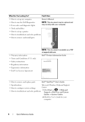
...; Regulatory information • Ergonomics information • End User License Agreement
NOTE: This document is available as a PDF at support.dell.com. Dell™ Product Information Guide
• How to remove and replace parts
Dell™ OptiPlex™ User's Guide
• Specifications
Microsoft Windows Help and Support
• How to configure system settings
Center
•...
Quick Reference
Guide - Page 65
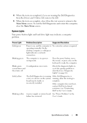
... mouse, or press a key on page 66). Solid yellow
The Dell Diagnostics is running If the Dell Diagnostics is required. User's Guide. incorrectly installed.
Quick Reference Guide
65
Blinking yellow A power supply or system board See "Power Problems" in a powersaving mode.
System Lights
Your power button light and hard drive light may be faulty or
complete...
User's Guide - Page 14
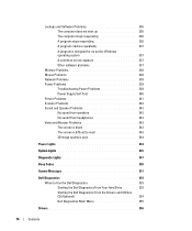
... 338 Mouse Problems 338 Network Problems 339 Power Problems 339
Troubleshooting Power Problems 339 Power Supply Self-Test 340 Printer Problems 341 Scanner...Power Lights 344
System Lights 345
Diagnostic Lights 347
Beep Codes 350
System Messages 351
Dell Diagnostics 353 When to Use the Dell Diagnostics 353 Starting the Dell Diagnostics From Your Hard Drive . . . . . 353 Starting the Dell...
User's Guide - Page 18
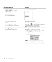
...; Enter the Express Service Code to troubleshoot and solve problems
• Service Tag and Express Service Code • Microsoft Windows License Label
Find It Here Dell™ Product Information Guide
Dell™ OptiPlex™ User's Guide Microsoft Windows Help and Support Center
1 Click Start or → Help and Support→...
User's Guide - Page 29
...
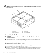
3
2
1
4
5
6 7
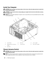
1 optical drive
4 optional chassis-intrusion switch
7 hard drive
2 disk drive 5 system board
3 power supply 6 heat sink assembly
Chassis Intrusion Switch
CAUTION: Before you begin any of the procedures in this section, follow the safety instructions located in ... Information Guide. it may not be present on mini tower, desktop and small form factor computers;
User's Guide - Page 81
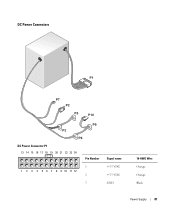
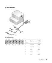
DC Power Connectors
DC Power Connector P1 13 14 15 16 17 18 19 20 21 22 23 24
1 2 3 4 5 6 7 8 9 10 11 12
Pin Number 1 2 3
Signal name +3.3 VDC +3.3 VDC GND
18-AWG Wire Orange Orange Black
Power Supply
81
User's Guide - Page 82
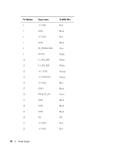
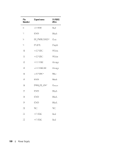
Pin Number 4 5 6 7 8 9 10 11 12 13 14 15 16 17 18 19 20 21 22
Signal name +5 VDC GND +5 VDC GND PS_PWRGOOD P5AUX V_12P0_DIG V_12P0_DIG +3.3 VDC +3.3VDC/SE* -12 VDC GND PWR_PS_ON GND GND GND NC +5 VDC +5 VDC
18-AWG Wire Red Black Red Black Gray Purple White White Orange Orange Blue Black Green Black Black Black NC Red Red
82
Power Supply
User's Guide - Page 83
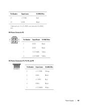
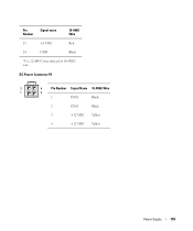
... Wire
23
+5 VDC
Red
24
GND
Black
*Optional wire. DC Power Connector P2
3
4
Pin Number Signal Name 18-AWG Wire
1
2
1
GND
Black
2
GND
Black
3
+12 VADC Yellow
4
+12 VADC Yellow
DC Power Connectors P3, P5, P8, and P9
Pin Number Signal name 18-AWG Wire
1
+3.3 VDC Orange
2
GND
Black
3
+5 VDC
Red
4
GND
Black
5
+12 VBDC White
Power Supply...
User's Guide - Page 84
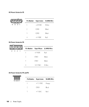
DC Power Connector P7
4 321
Pin Number Signal Name 22-AWG Wire
1
+5 VDC
Red
2
GND
Black
3
GND
Black
4
+12 VDC Yellow
DC Power Connector P10
Pin Number Signal name 18-AWG Wire
1
+12 VBDC White
2
GND
Black
3
GND
Black
4
+5 VDC
Red
84
Power Supply
User's Guide - Page 92
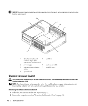
...drive bays (media card
5 card slots
reader or floppy drive,
optical drive and hard drive)
2 power supply
6 heat sink assembly
3 optional chassis-intrusion 7 front I/O panel switch
4 system board
Chassis Intrusion Switch...Remove the computer cover (see "Removing the Computer Cover" on mini tower, desktop, and small form factor computers;
Removing the Chassis Intrusion Switch
1 Follow ...
User's Guide - Page 101
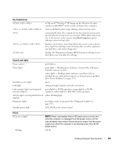
... by the remote boot environment (PXE) rather than from one of power from the power supply even when the computer is unplugged from the AC power source.
280 W
Desktop Computer Specifications
101 blinking green indicates a sleep mode; solid amber indicates an internal power problem (See "Power Problems" on page 339.)
hard drive access light
green
Link light...
User's Guide - Page 102
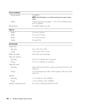
... Maximum shock: Operating
Storage
Altitude: Operating Storage
Airborne contaminant level
955 BTU/hr NOTE: Heat dissipation is calculated based upon the power supply rating. manual selection power supplies - 90 to 135 V at 50/60 Hz; 180 to 265 V at 50/60 Hz 3-V CR2032 lithium coin cell
...10,668 m (-50 to 35,000 ft) G2 or lower as defined by ISA-S71.04-1985
102
Desktop Computer Specifications
User's Guide - Page 157
DC Power Connectors
DC Power Connector P1 13 14 15 16 17 18 19 20 21 22 23 24
1 2 3 4 5 6 7 8 9 10 11 12
Pin Number
Signal name
1
+3.3 VDC
2
+3.3 VDC
3
GND
4
+5 VDC
5
GND
18-AWG Wire Orange Orange Black Red Black
Power Supply
157
User's Guide - Page 158
Pin Number
Signal name
18-AWG Wire
6
+5 VDC
Red
7
GND
Black
8
PS_PWRGOOD* Gray
9
P5AUX
Purple
10
+12 VDC
White
11
+12 VDC
White
12
+3.3 VDC
Orange
13
+3.3 VDC/SE
Orange
14
+12 VDC*
Blue
15
GND
Black
16
PWR_PS_ON* Green
17
GND
Black
18
GND
Black
19
GND
Black
20
NC
NC
21
+5 VDC
Red
22
+5 VDC
Red
158
Power Supply
User's Guide - Page 159
DC Power Connector P2
3
4
Pin Number Signal Name 18-AWG Wire
1
2
1
GND
Black
2
GND
Black
3
+12 VDC Yellow
4
+12 VDC Yellow
Power Supply
159 Pin Number
Signal name
18-AWG Wire
23
+5 VDC
24
GND
Red Black
*Use 22-AWG wire instead of 18-AWG wire.
User's Guide - Page 160
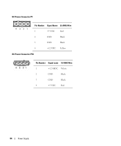
DC Power Connector P3
Pin Number Signal name 18-AWG Wire
1
+12VDC Yellow
2
GND
Black
3
GND
Black
4
+5 VDC
Red
DC Power Connector P4
4 321
Pin Number Signal Name 22-AWG Wire
1
+5 VDC
Red
2
GND
Black
3
GND
Black
4
+12 VDC Yellow
DC Power Connector P5 and P6
Pin Number Signal name 18-AWG Wire
1
+3.3 VDC Orange
2
GND
Black
3
+5 VDC
Red
160
Power Supply
User's Guide - Page 170
...197). 4 Disconnect the chassis intrusion switch cable from the system board.
3
4
2
1
5 6
1 drive-release latch 2 optical drive 3 power supply and fan
4 hard drive 5 system board 6 heat sink assembly
Chassis Intrusion Switch
CAUTION: Before you begin any of the connector as you pull ... on your computer. it may not be present on mini tower, desktop, and small form factor computers;
User's Guide - Page 269
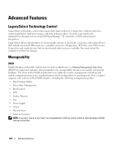
...system setup, Dell OpenManage™ IT Assistant, or Dell custom-factory integration. Manageability
DASH
DASH (Desktop and mobile Architecture for System Hardware) is a Desktop Management Task... management profiles: • Base Desktop Mobile • Power State Management • Boot Control • CPU • System Memory • Fan • Power Supply • Sensor • Physical...
User's Guide - Page 341
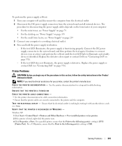
... is USB. NOTE: If you begin any of your computer:
• For the mini tower, see "Power Supply" on page 79
• For the desktop, see "Power Supply" on page 155 • For the small form factor, see "Contacting Dell" on page 370). TE ST T H E E L E CT R I O N - ENSURE THAT THE PRINTER IS TURNED ON
CHECK THE PRINTER...
User's Guide - Page 373
... harmful interference in accordance with the manufacturer's instruction manual, may cause interference with the FCC regulations:
• Product name: Dell™ OptiPlex™ 755
• Model numbers: DCTR, DCNE, DCSM, DCCY
• Company name: Dell Inc. FCC Notices (US Only)
373
FCC Notices (U.S. However, there is provided on , you are designed to the following...
Similar Questions


Dell Optiplex 790 Power Supply Failure
When pushing the power button on the unit nothing happens. Is this probably the power supply.
When pushing the power button on the unit nothing happens. Is this probably the power supply.
(Posted by frankcurtiss 10 years ago)

How To Hook Up The Wires On My Optiplex 755 Processr
connection guide for my optiplex processer
connection guide for my optiplex processer
(Posted by rschoenauer 10 years ago)


Power Supply Connection Cables
I removed the power supply and misplaced some of my post it notes. I can't figure out for sure where...
I removed the power supply and misplaced some of my post it notes. I can't figure out for sure where...
(Posted by Slr29 11 years ago)