
User's Guide
Page 27
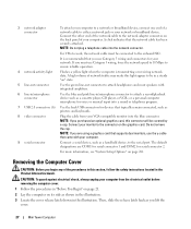
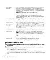
... the network cable to the network adapter connector on " state. 5 line-out connector Use the green line-out connector to the serial port. A click indicates that typically remain connected, such as shown in the illustration. 3 Locate the cover release latch shown in the Product Information...the connector on page 281. or a personal computer microphone for voice or musical input into a sound or telephony program. 7 USB 2.0 connectors (6) Use the back USB connectors for your network or broadband device. Then, slide the release latch back as a handheld device, to attach headphones and...
... the network cable to the network adapter connector on " state. 5 line-out connector Use the green line-out connector to the serial port. A click indicates that typically remain connected, such as shown in the illustration. 3 Locate the cover release latch shown in the Product Information...the connector on page 281. or a personal computer microphone for voice or musical input into a sound or telephony program. 7 USB 2.0 connectors (6) Use the back USB connectors for your network or broadband device. Then, slide the release latch back as a handheld device, to attach headphones and...
User's Guide
Page 37
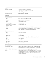
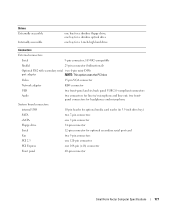
...; Two SATA optical drives One eSATA drive (optional) Connectors External connectors: Serial Parallel Video Network adapter Optional PS/2 with secondary serial port adapter USB Audio System board connectors: SATA eSATA Floppy drive Serial Fan PCI 2.2 PCI Express Front panel 9-pin connector; 16550C-compatible 25-pin ... 15-pin VGA connector RJ45 connector two 6-pin mini-DINs two front-panel and six back panel USB 2.0-compliant connectors two connectors for optional second PS/2 serial port card 5-pin connector three 120-pin connectors one 120-pin (x16) connector 40-pin connector Key Combinations...
...; Two SATA optical drives One eSATA drive (optional) Connectors External connectors: Serial Parallel Video Network adapter Optional PS/2 with secondary serial port adapter USB Audio System board connectors: SATA eSATA Floppy drive Serial Fan PCI 2.2 PCI Express Front panel 9-pin connector; 16550C-compatible 25-pin ... 15-pin VGA connector RJ45 connector two 6-pin mini-DINs two front-panel and six back panel USB 2.0-compliant connectors two connectors for optional second PS/2 serial port card 5-pin connector three 120-pin connectors one 120-pin (x16) connector 40-pin connector Key Combinations...
User's Guide
Page 90
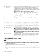
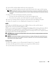
...must be covered by a cap. or a personal computer microphone for voice or musical input into a sound or telephony program. 7 USB 2.0 connectors (6) Use the back USB connectors for devices that the network cable has been securely attached. The default designations are using a graphics card that supports dual monitors,...network adapter connector on the back panel, remove the padlock. 3 Locate the cover release latch shown in /microphone connector to the serial port. NOTE: If you are COM1 for serial connector 1 and COM2 for your network. Connect the other end of the network cable ...
...must be covered by a cap. or a personal computer microphone for voice or musical input into a sound or telephony program. 7 USB 2.0 connectors (6) Use the back USB connectors for devices that the network cable has been securely attached. The default designations are using a graphics card that supports dual monitors,...network adapter connector on the back panel, remove the padlock. 3 Locate the cover release latch shown in /microphone connector to the serial port. NOTE: If you are COM1 for serial connector 1 and COM2 for your network. Connect the other end of the network cable ...
User's Guide
Page 100
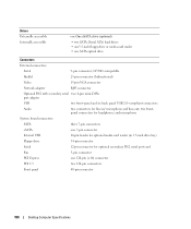
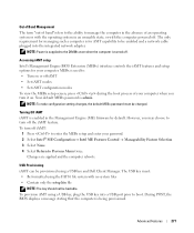
...three 7-pin connectors eSATA one 7-pin connector Internal USB 10-pin header for optional media card reader (in 3.5-inch drive bay) Floppy drive 34-pin connector Serial 12-pin connector for optional secondary PS/2 serial port card Fan 5-pin connector PCI Express one SATA ...Video 15-pin VGA connector Network adapter RJ45 connector Optional PS/2 with secondary serial two 6-pin mini-DINs port adapter USB two front-panel and six back panel USB 2.0-compliant connectors Audio two connectors for line-in/ microphone and line-out; Drives Externally accessible Internally accessible ...
...three 7-pin connectors eSATA one 7-pin connector Internal USB 10-pin header for optional media card reader (in 3.5-inch drive bay) Floppy drive 34-pin connector Serial 12-pin connector for optional secondary PS/2 serial port card Fan 5-pin connector PCI Express one SATA ...Video 15-pin VGA connector Network adapter RJ45 connector Optional PS/2 with secondary serial two 6-pin mini-DINs port adapter USB two front-panel and six back panel USB 2.0-compliant connectors Audio two connectors for line-in/ microphone and line-out; Drives Externally accessible Internally accessible ...
User's Guide
Page 168
...release latch shown in this connector will be covered by a cap. Then, slide the release latch back as a handheld device, to the serial port. If you must be in a steady "on" state. 5 line-out connector Use the green line-out connector (available on computers with integrated ...connector (available on the graphics card. or a personal computer microphone for voice or musical input into a sound or telephony program. 7 USB 2.0 connectors (6) Use the back USB connectors for your network. NOTE: Do not plug a telephone cable into the blue connector. A high volume of network traffic may ...
...release latch shown in this connector will be covered by a cap. Then, slide the release latch back as a handheld device, to the serial port. If you must be in a steady "on" state. 5 line-out connector Use the green line-out connector (available on computers with integrated ...connector (available on the graphics card. or a personal computer microphone for voice or musical input into a sound or telephony program. 7 USB 2.0 connectors (6) Use the back USB connectors for your network. NOTE: Do not plug a telephone cable into the blue connector. A high volume of network traffic may ...
User's Guide
Page 177
...a slimline optical drive one bay for a slimline floppy drive; Video 15-pin VGA connector Network adapter RJ45 connector USB two front-panel and six back panel USB 2.0-compliant connectors Audio two connectors for line-in 3.5-inch drive bay) SATA two 7-pin connectors eSATA one 7-pin...card reader (in / microphone and line-out; two frontpanel connectors for headphones and microphone System board connectors: internal USB 10-pin header for optional secondary serial port card Fan two 5-pin connectors PCI 2.3 one 120-pin connector PCI Express one 164-pin (x16) connector ...
...a slimline optical drive one bay for a slimline floppy drive; Video 15-pin VGA connector Network adapter RJ45 connector USB two front-panel and six back panel USB 2.0-compliant connectors Audio two connectors for line-in 3.5-inch drive bay) SATA two 7-pin connectors eSATA one 7-pin...card reader (in / microphone and line-out; two frontpanel connectors for headphones and microphone System board connectors: internal USB 10-pin header for optional secondary serial port card Fan two 5-pin connectors PCI 2.3 one 120-pin connector PCI Express one 164-pin (x16) connector ...
User's Guide
Page 193
5 Ease the PS/2 serial-port adapter bracket out of your computer's electronic components. NOTICE: To prevent static damage to components inside your computer, discharge static electricity from your computer. CAUTION: ... computer prior to connecting the device to maintain FCC certification of the procedures in this section, follow the safety instructions located in the top of USB. You can do so by closing the card retention latch and snapping it into the desired eSATA opening . NOTE: Installing filler brackets over empty card...
5 Ease the PS/2 serial-port adapter bracket out of your computer's electronic components. NOTICE: To prevent static damage to components inside your computer, discharge static electricity from your computer. CAUTION: ... computer prior to connecting the device to maintain FCC certification of the procedures in this section, follow the safety instructions located in the top of USB. You can do so by closing the card retention latch and snapping it into the desired eSATA opening . NOTE: Installing filler brackets over empty card...
User's Guide
Page 271
...and a network cable plugged into a USB port prior to boot. Accessing iAMT setup Intel's Management Engine BIOS Extension (MEBx) interface controls the iAMT features and setup options for AMT capability to be provisioned using a USB key, plug the USB key into the integrated network adapter. ... an operating system or with the operating system in the Management Engine (ME) firmware by default. To provision AMT using a USB key and Dell Client Manager. Advanced Features 271 Your default MEBx password is being provisioned. The only requirement for managing such a computer is for...
...and a network cable plugged into a USB port prior to boot. Accessing iAMT setup Intel's Management Engine BIOS Extension (MEBx) interface controls the iAMT features and setup options for AMT capability to be provisioned using a USB key, plug the USB key into the integrated network adapter. ... an operating system or with the operating system in the Management Engine (ME) firmware by default. To provision AMT using a USB key and Dell Client Manager. Advanced Features 271 Your default MEBx password is being provisioned. The only requirement for managing such a computer is for...
User's Guide
Page 283
... video controller. Rear Quad/Triad USB Enables or disables the upper USB ports on the back of the computer. (On default) Rear Dual USB Enables or disables the lower USB ports on the back of the computer. (On default) Front USB Enables or disables the front USB ports. (On default) PCI Slots ...Enables or disables all PCI and PCI Express slots. (On default) LPT Port Mode (PS/2 default) Determines...
... video controller. Rear Quad/Triad USB Enables or disables the upper USB ports on the back of the computer. (On default) Rear Dual USB Enables or disables the lower USB ports on the back of the computer. (On default) Front USB Enables or disables the front USB ports. (On default) PCI Slots ...Enables or disables all PCI and PCI Express slots. (On default) LPT Port Mode (PS/2 default) Determines...
User's Guide
Page 288
... the Boot Sequence menu option and press to access the popup menu. Booting to a USB Device NOTE: To boot to a USB memory key, highlight USB Device and press . Memory Key 1 Insert the memory key into a USB port and restart the computer. 2 When F12 = Boot Menu appears in the upper-right ...corner of devices. 4 Press the spacebar to enable or disable a device. (Enabled devices have a checkmark.) 5 Press or to a USB device, the device must be bootable. If you ...
... the Boot Sequence menu option and press to access the popup menu. Booting to a USB Device NOTE: To boot to a USB memory key, highlight USB Device and press . Memory Key 1 Insert the memory key into a USB port and restart the computer. 2 When F12 = Boot Menu appears in the upper-right ...corner of devices. 4 Press the spacebar to enable or disable a device. (Enabled devices have a checkmark.) 5 Press or to a USB device, the device must be bootable. If you ...
User's Guide
Page 341
Replace the power supply or contact Dell (see "Contacting Dell" on page 370). - See the printer documentation for your computer to the following port(s): setting is listed, right-click the printer icon. 3 Click Properties→ Ports. To perform the power supply self-test: 1 Turn your computer: ...8594; Control Panel→ Printers and Other Hardware→ View installed printers or fax printers. 2 If the printer is USB. Solving Problems 341 For a USB printer, ensure that the Print to a working by testing it with another device, such as a lamp. Printer Problems CAUTION...
Replace the power supply or contact Dell (see "Contacting Dell" on page 370). - See the printer documentation for your computer to the following port(s): setting is listed, right-click the printer icon. 3 Click Properties→ Ports. To perform the power supply self-test: 1 Turn your computer: ...8594; Control Panel→ Printers and Other Hardware→ View installed printers or fax printers. 2 If the printer is USB. Solving Problems 341 For a USB printer, ensure that the Print to a working by testing it with another device, such as a lamp. Printer Problems CAUTION...
User's Guide
Page 383
... editor. The main circuit board in the BIOS, such as a USB-compatible keyboard, mouse, joystick, scanner, set of the platform base that may also provide voltage regulation. Enables Windows programs to a multi-port hub that supports resolutions up to your computer. for video cards and... digital audio device to save energy. S/PDIF - super-extended graphics array - A utility that contain only text; uninterruptible power supply - USB - USB devices can be connected and disconnected while the computer is on , and they can also be protected by acting as file and e-mail ...
... editor. The main circuit board in the BIOS, such as a USB-compatible keyboard, mouse, joystick, scanner, set of the platform base that may also provide voltage regulation. Enables Windows programs to a multi-port hub that supports resolutions up to your computer. for video cards and... digital audio device to save energy. S/PDIF - super-extended graphics array - A utility that contain only text; uninterruptible power supply - USB - USB devices can be connected and disconnected while the computer is on , and they can also be protected by acting as file and e-mail ...


