Owner's Manual (Desktop)
Page 3
... Battery...13 Removing The Hard Drive...13 Installing The Hard Drive...15 Removing The Optical Drive...15 Installing The Optical Drive...17 Removing The Speaker...17 Installing The Speaker...18 Removing The Power Supply Unit...18 Installing The Power Supply Unit...22 Removing The Heat Sink...23 Installing The Heat Sink...24...
... Battery...13 Removing The Hard Drive...13 Installing The Hard Drive...15 Removing The Optical Drive...15 Installing The Optical Drive...17 Removing The Speaker...17 Installing The Speaker...18 Removing The Power Supply Unit...18 Installing The Power Supply Unit...22 Removing The Heat Sink...23 Installing The Heat Sink...24...

Owner's Manual (Desktop)
Page 17
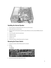
Follow the procedures in After Working Inside Your Computer. Installing The Optical Drive 1. Install the cover. 5. Follow the procedures in Before Working Inside Your Computer. 2. Remove the cover. 3. Install the front bezel. 4. Connect the data cable and the power cable to the optical drive. 3. Disconnect the speaker and unthread it. 17 Push the optical drive from the front towards the back of the computer. 2. Removing The Speaker 1.
Follow the procedures in After Working Inside Your Computer. Installing The Optical Drive 1. Install the cover. 5. Follow the procedures in Before Working Inside Your Computer. 2. Remove the cover. 3. Install the front bezel. 4. Connect the data cable and the power cable to the optical drive. 3. Disconnect the speaker and unthread it. 17 Push the optical drive from the front towards the back of the computer. 2. Removing The Speaker 1.

Owner's Manual (Desktop)
Page 18
Press down the speaker-securing tab and slide the speaker upwards to remove it . 2. Thread the speaker cable into the chassis clip. 3. Connect the speaker cable to secure it . Follow the procedures in After Working Inside Your Computer. 4. Install the cover. 5. Remove the a) cover b) hard drive c) optical drive 18 Press the speaker-securing tab and slide the speaker downward to the system board. 4. Follow the procedures in Before Working Inside Your Computer. 2. Installing The Speaker 1. Removing The Power Supply Unit 1.
Press down the speaker-securing tab and slide the speaker upwards to remove it . 2. Thread the speaker cable into the chassis clip. 3. Connect the speaker cable to secure it . Follow the procedures in After Working Inside Your Computer. 4. Install the cover. 5. Remove the a) cover b) hard drive c) optical drive 18 Press the speaker-securing tab and slide the speaker downward to the system board. 4. Follow the procedures in Before Working Inside Your Computer. 2. Installing The Speaker 1. Removing The Power Supply Unit 1.
Owner's Manual (Desktop)
Page 36
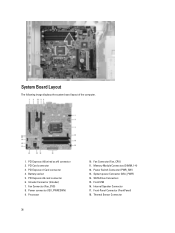
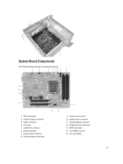
... The following image displays the system board layout of the computer. 1. Power connector (12V_PWRCONN) 9. Memory Module Connectors (DIMM_1-4) 12. System power Connector (Mini_PWR) 14. Internal Speaker Connector 17. Battery socket 5. Fan Connector (Fan_CPU) 11. SATA Drive Connectors 15. Fan Connector (Fan_SYS) 8. Power Switch Connector (PWR_SW) 13. Thermal Sensor Connector PCI Express...
... The following image displays the system board layout of the computer. 1. Power connector (12V_PWRCONN) 9. Memory Module Connectors (DIMM_1-4) 12. System power Connector (Mini_PWR) 14. Internal Speaker Connector 17. Battery socket 5. Fan Connector (Fan_CPU) 11. SATA Drive Connectors 15. Fan Connector (Fan_SYS) 8. Power Switch Connector (PWR_SW) 13. Thermal Sensor Connector PCI Express...

Owner's Manual (Desktop)
Page 61
... connector Processor Fan one 5-pin connector Service mode jumper one 2-pin connector Password clear jumper one 2-pin connector RTC reset jumper one 2-pin connector Internal speaker one 5-pin connector Intruder connector one 3-pin connector Power connector: Mini-Tower, Desktop, Small Form Factor one 24-pin and one 4-pin connector Ultra Small...
... connector Processor Fan one 5-pin connector Service mode jumper one 2-pin connector Password clear jumper one 2-pin connector RTC reset jumper one 2-pin connector Internal speaker one 5-pin connector Intruder connector one 3-pin connector Power connector: Mini-Tower, Desktop, Small Form Factor one 24-pin and one 4-pin connector Ultra Small...

Owner's Manual (Mini-Tower)
Page 3
... Battery...13 Removing the Hard Drive...14 Installing the Hard Drive...15 Removing the Optical Drive...15 Installing the Optical Drive...17 Removing the Speaker...17 Installing the Speaker...18 Removing the Power Supply...18 Installing the Power Supply...21 Removing the Heat Sink...21 Installing the Heat Sink...22 Removing the...
... Battery...13 Removing the Hard Drive...14 Installing the Hard Drive...15 Removing the Optical Drive...15 Installing the Optical Drive...17 Removing the Speaker...17 Installing the Speaker...18 Removing the Power Supply...18 Installing the Power Supply...21 Removing the Heat Sink...21 Installing the Heat Sink...22 Removing the...

Owner's Manual (Mini-Tower)
Page 17
... steps 4 to 5 to the back of the computer till it is secured by the optical-drive latch. 2. Disconnect and release the speaker cable from the front toward the back of the optical drive. 3. Follow the procedures in After Working Inside Your Computer. Push the optical drive from ...
... steps 4 to 5 to the back of the computer till it is secured by the optical-drive latch. 2. Disconnect and release the speaker cable from the front toward the back of the optical drive. 3. Follow the procedures in After Working Inside Your Computer. Push the optical drive from ...

Owner's Manual (Mini-Tower)
Page 18
4. Install the cover. 4. Removing the Power Supply 1. Slide the speaker downwards into the chassis clip and connect the speaker cable to the system board. 3. Release and disconnect the power cable from the optical drive(s). 18 Thread the speaker cable into its slot to remove. Follow the procedures in Before Working Inside Your Computer. 2. Remove the cover. 3. Follow the procedures in After Working Inside Your Computer. Installing the Speaker 1. Press down the speaker-securing tab and slide the speaker upwards to secure it. 2.
4. Install the cover. 4. Removing the Power Supply 1. Slide the speaker downwards into the chassis clip and connect the speaker cable to the system board. 3. Release and disconnect the power cable from the optical drive(s). 18 Thread the speaker cable into its slot to remove. Follow the procedures in Before Working Inside Your Computer. 2. Remove the cover. 3. Follow the procedures in After Working Inside Your Computer. Installing the Speaker 1. Press down the speaker-securing tab and slide the speaker upwards to secure it. 2.
Owner's Manual (Mini-Tower)
Page 33
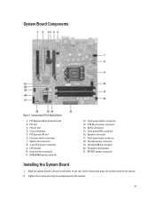
... to the port connectors on the rear of the chassis and place the system board in the chassis. 2. PCI Express x16 slot (wired as x4) 2. Speaker connector 17. Thermal sensor connector 19. Align the system board to the chassis. 33 System Board Components Figure 1. Front power-button connector 13. Coin-cell...
... to the port connectors on the rear of the chassis and place the system board in the chassis. 2. PCI Express x16 slot (wired as x4) 2. Speaker connector 17. Thermal sensor connector 19. Align the system board to the chassis. 33 System Board Components Figure 1. Front power-button connector 13. Coin-cell...

Owner's Manual (Mini-Tower)
Page 57
... connector Processor Fan one 5-pin connector Service mode jumper one 2-pin connector Password clear jumper one 2-pin connector RTC reset jumper one 2-pin connector Internal speaker one 5-pin connector Intruder connector one 3-pin connector Power connector: Mini-Tower, Desktop, Small Form Factor one 24-pin and one 4-pin connector Ultra Small...
... connector Processor Fan one 5-pin connector Service mode jumper one 2-pin connector Password clear jumper one 2-pin connector RTC reset jumper one 2-pin connector Internal speaker one 5-pin connector Intruder connector one 3-pin connector Power connector: Mini-Tower, Desktop, Small Form Factor one 24-pin and one 4-pin connector Ultra Small...

Owner's Manual (Small Form Factor)
Page 3
... Removing the Coin-Cell Battery...16 Installing the Coin-Cell Battery...17 Removing the System Fan...17 Installing the System Fan...19 Removing the Speaker...19 Installing the Speaker...20 Removing the Power-Switch Cable...20 Installing the Power-Switch Cable...21 Removing the Input/Output (I/O) Panel...21 Installing the Input/Output...
... Removing the Coin-Cell Battery...16 Installing the Coin-Cell Battery...17 Removing the System Fan...17 Installing the System Fan...19 Removing the Speaker...19 Installing the Speaker...20 Removing the Power-Switch Cable...20 Installing the Power-Switch Cable...21 Removing the Input/Output (I/O) Panel...21 Installing the Input/Output...

Owner's Manual (Small Form Factor)
Page 19
... Inside Your Computer. Install the: a) drive cage b) front bezel c) cover 5. Pass the grommets through the restraint and connect it . 19 Press the speaker-securing tab, and slide the speaker towards the right of the computer to secure them in Before Working Inside Your Computer. 2. Installing the System Fan 1. Thread the fan cable...
... Inside Your Computer. Install the: a) drive cage b) front bezel c) cover 5. Pass the grommets through the restraint and connect it . 19 Press the speaker-securing tab, and slide the speaker towards the right of the computer to secure them in Before Working Inside Your Computer. 2. Installing the System Fan 1. Thread the fan cable...

Owner's Manual (Small Form Factor)
Page 20
Place the speaker at the appropriate location on the chassis rear. 2. Connect the speaker cable to secure it. 3. Follow the procedures in After Working Inside Your Computer. Remove the: a) cover b) front bezel c) drive cage 3. Press the speaker-securing tab and slide the speaker towards the left of the computer to the system board. 4. Disconnect the power-switch cable from the system board. 20 Install the: a) drive cage b) front bezel c) cover 5. Follow the procedures in Before Working Inside Your Computer. 2. Removing the Power-Switch Cable 1. Installing the Speaker 1.
Place the speaker at the appropriate location on the chassis rear. 2. Connect the speaker cable to secure it. 3. Follow the procedures in After Working Inside Your Computer. Remove the: a) cover b) front bezel c) drive cage 3. Press the speaker-securing tab and slide the speaker towards the left of the computer to the system board. 4. Disconnect the power-switch cable from the system board. 20 Install the: a) drive cage b) front bezel c) cover 5. Follow the procedures in Before Working Inside Your Computer. 2. Removing the Power-Switch Cable 1. Installing the Speaker 1.
Owner's Manual (Small Form Factor)
Page 31
system fan connector 10. SATA connectors 14. power connector 4. processor 5. PCI Express x16 connectors 13. memory module connectors 9. internal speaker connector 12. coin-cell battery 31 system fan connector 6. system power connector 11. System Board Components The following image displays the system board layout. 1. RTC reset jumper 2. intrusion-switch connector 3. password jumper 7. power switch connector 8. front-USB connector 15.
system fan connector 10. SATA connectors 14. power connector 4. processor 5. PCI Express x16 connectors 13. memory module connectors 9. internal speaker connector 12. coin-cell battery 31 system fan connector 6. system power connector 11. System Board Components The following image displays the system board layout. 1. RTC reset jumper 2. intrusion-switch connector 3. password jumper 7. power switch connector 8. front-USB connector 15.
Owner's Manual (Small Form Factor)
Page 55
... connector Processor Fan one 5-pin connector Service mode jumper one 2-pin connector Password clear jumper one 2-pin connector RTC reset jumper one 2-pin connector Internal speaker one 5-pin connector Intruder connector one 3-pin connector Power connector: Mini-Tower, Desktop, Small Form Factor one 24-pin and one 4-pin connector Ultra Small...
... connector Processor Fan one 5-pin connector Service mode jumper one 2-pin connector Password clear jumper one 2-pin connector RTC reset jumper one 2-pin connector Internal speaker one 5-pin connector Intruder connector one 3-pin connector Power connector: Mini-Tower, Desktop, Small Form Factor one 24-pin and one 4-pin connector Ultra Small...
Owner's Manual (Ultra Small Form Factor)
Page 3
... the Coin-Cell Battery...15 Installing the Coin-Cell Battery...15 Removing the System Fan...16 Installing the System Fan...17 Removing the Speaker...17 Installing the Internal Speaker...19 Removing the Power Switch...19 Installing the Power Switch...20 Removing the Input/Output(I/O) Panel...20 Installing the Input/Output(I/O) Panel...21...
... the Coin-Cell Battery...15 Installing the Coin-Cell Battery...15 Removing the System Fan...16 Installing the System Fan...17 Removing the Speaker...17 Installing the Internal Speaker...19 Removing the Power Switch...19 Installing the Power Switch...20 Removing the Input/Output(I/O) Panel...20 Installing the Input/Output(I/O) Panel...21...

Owner's Manual (Ultra Small Form Factor)
Page 17
... the system board. 5. Follow the procedures in the chassis. 2. Installing the System Fan 1. Tighten the screws that secure the fan to the chassis. 3. 5. Removing the Speaker 1. Remove: a) cover b) front bezel c) drive cage 3. Place the system fan in After Working Inside Your Computer. Install the front bezel. 7. Follow the procedures in Before...
... the system board. 5. Follow the procedures in the chassis. 2. Installing the System Fan 1. Tighten the screws that secure the fan to the chassis. 3. 5. Removing the Speaker 1. Remove: a) cover b) front bezel c) drive cage 3. Place the system fan in After Working Inside Your Computer. Install the front bezel. 7. Follow the procedures in Before...

Owner's Manual (Ultra Small Form Factor)
Page 18
Remove the speaker from beneath the system fan cable and Wireless Local Area Network (WLAN) antennae (if installed). 5. Release the latch and rotate the speaker. 6. 4. Pull out the speaker cable from the chassis. 18
Remove the speaker from beneath the system fan cable and Wireless Local Area Network (WLAN) antennae (if installed). 5. Release the latch and rotate the speaker. 6. 4. Pull out the speaker cable from the chassis. 18
Owner's Manual (Ultra Small Form Factor)
Page 19
... 8. Remove: a) cover b) front bezel c) drive cage 3. Removing the Power Switch 1. Follow the procedures in place. 3. Installing the Internal Speaker 1. Install the front bezel. 7. Follow the procedures in After Working Inside Your Computer. Disconnect the power-switch cable from the chassis. 19 Route the... speaker cable beneath the system fan cable and Wireless Local Area network (WLAN) antennae (if installed). 4. Connect the speaker cable to the system board. 5. Place the speaker on the appropriate location of the rear end of the...
... 8. Remove: a) cover b) front bezel c) drive cage 3. Removing the Power Switch 1. Follow the procedures in place. 3. Installing the Internal Speaker 1. Install the front bezel. 7. Follow the procedures in After Working Inside Your Computer. Disconnect the power-switch cable from the chassis. 19 Route the... speaker cable beneath the system fan cable and Wireless Local Area network (WLAN) antennae (if installed). 4. Connect the speaker cable to the system board. 5. Place the speaker on the appropriate location of the rear end of the...

Owner's Manual (Ultra Small Form Factor)
Page 27
.... 7. Ensure the processor is properly seated. 2. Remove: a) cover b) front bezel c) drive cage d) system fan e) power supply f) heat sink g) processor h) memory i) input/output panel j) WLAN card k) speaker 3. Disconnect all the cables connected to secure it with the retention hook. 3. Insert the processor into the processor socket. Install the drive cage. 5. Removing the...
.... 7. Ensure the processor is properly seated. 2. Remove: a) cover b) front bezel c) drive cage d) system fan e) power supply f) heat sink g) processor h) memory i) input/output panel j) WLAN card k) speaker 3. Disconnect all the cables connected to secure it with the retention hook. 3. Insert the processor into the processor socket. Install the drive cage. 5. Removing the...


