Setup and Quick Reference Guide
Page 4
3 Specifications - Mini Tower Computer 25 4 Specifications - Desktop Computer 31 5 Troubleshooting Tips 37 Using the Hardware Troubleshooter 37 Tips 37 Power Problems 37 Memory Problems 39 Lockups and Software Problems 39 Dell Technical Update Service 41 Dell Support Utility 41 Dell Diagnostics 41 6 Reinstalling Software 43 Drivers 43 Identifying Drivers 43 Reinstalling Drivers and Utilities 43 Restoring Your Operating System 45 Using Microsoft® Windows® System Restore . . . 46 Using Dell Factory Image Restore 46 Using the Operating System Media 47 4 Contents
3 Specifications - Mini Tower Computer 25 4 Specifications - Desktop Computer 31 5 Troubleshooting Tips 37 Using the Hardware Troubleshooter 37 Tips 37 Power Problems 37 Memory Problems 39 Lockups and Software Problems 39 Dell Technical Update Service 41 Dell Support Utility 41 Dell Diagnostics 41 6 Reinstalling Software 43 Drivers 43 Identifying Drivers 43 Reinstalling Drivers and Utilities 43 Restoring Your Operating System 45 Using Microsoft® Windows® System Restore . . . 46 Using Dell Factory Image Restore 46 Using the Operating System Media 47 4 Contents
Setup and Quick Reference Guide
Page 7
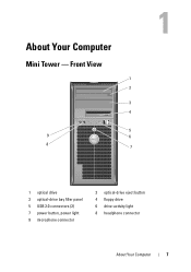
About Your Computer Mini Tower - Front View 1 2 3 4 5 9 6 8 7 1 optical drive 3 optical-drive bay filler panel 5 USB 2.0 connectors (2) 7 power button, power light 9 microphone connector 2 optical-drive eject button 4 floppy drive 6 drive-activity light 8 headphone connector About Your Computer 7
About Your Computer Mini Tower - Front View 1 2 3 4 5 9 6 8 7 1 optical drive 3 optical-drive bay filler panel 5 USB 2.0 connectors (2) 7 power button, power light 9 microphone connector 2 optical-drive eject button 4 floppy drive 6 drive-activity light 8 headphone connector About Your Computer 7
Setup and Quick Reference Guide
Page 8
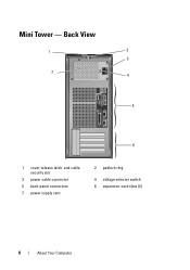
Mini Tower - Back View 1 2 3 7 4 5 6 1 cover-release latch, and cable security slot 3 power cable connector 5 back-panel connectors 7 power supply vent 2 padlock ring 4 voltage selector switch 6 expansion-card slots (4) 8 About Your Computer
Mini Tower - Back View 1 2 3 7 4 5 6 1 cover-release latch, and cable security slot 3 power cable connector 5 back-panel connectors 7 power supply vent 2 padlock ring 4 voltage selector switch 6 expansion-card slots (4) 8 About Your Computer
Setup and Quick Reference Guide
Page 10
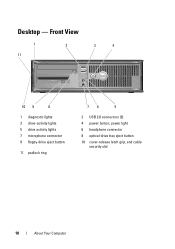
Front View 1 11 2 3 4 10 9 8 1 diagnostic lights 3 drive-activity lights 5 drive activity lights 7 microphone connector 9 floppy-drive eject button 11 padlock ring 76 5 2 USB 2.0 connectors (2) 4 power button, power light 6 headphone connector 8 optical-drive tray eject button 10 cover-release latch grip, and cable security slot 10 About Your Computer Desktop -
Front View 1 11 2 3 4 10 9 8 1 diagnostic lights 3 drive-activity lights 5 drive activity lights 7 microphone connector 9 floppy-drive eject button 11 padlock ring 76 5 2 USB 2.0 connectors (2) 4 power button, power light 6 headphone connector 8 optical-drive tray eject button 10 cover-release latch grip, and cable security slot 10 About Your Computer Desktop -

Setup and Quick Reference Guide
Page 11
Back View 1 2 3 4 5 6 1 expansion-card slots (3) 3 power connector 5 padlock ring 2 back-panel connectors 4 voltage selector switch 6 cover-release latch grip, and security cable slot About Your Computer 11 Desktop -
Back View 1 2 3 4 5 6 1 expansion-card slots (3) 3 power connector 5 padlock ring 2 back-panel connectors 4 voltage selector switch 6 cover-release latch grip, and security cable slot About Your Computer 11 Desktop -
Setup and Quick Reference Guide
Page 17
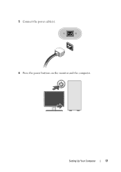
Setting Up Your Computer 17 5 Connect the power cable(s). 6 Press the power buttons on the monitor and the computer.
Setting Up Your Computer 17 5 Connect the power cable(s). 6 Press the power buttons on the monitor and the computer.
Setup and Quick Reference Guide
Page 28
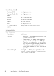
... hard drive or CD/DVD. 28 Specifications - This indication could be a system board or a power supply problem (see "Power Problems" on state • amber light - solid green for power-on page 37). Mini Tower Computer A solid amber light when the computer does not start indicates ...cannot start initialization. Connectors (continued) Front panel USB Front panel audio HDA header Processor Memory Power 12 V Power LAN on motherboard (LOM) Controls and Lights Front of computer: Power button Power light Drive activity light two 10-pin connectors one 10-pin connector one 775-pin connector ...
... hard drive or CD/DVD. 28 Specifications - This indication could be a system board or a power supply problem (see "Power Problems" on state • amber light - solid green for power-on page 37). Mini Tower Computer A solid amber light when the computer does not start indicates ...cannot start initialization. Connectors (continued) Front panel USB Front panel audio HDA header Processor Memory Power 12 V Power LAN on motherboard (LOM) Controls and Lights Front of computer: Power button Power light Drive activity light two 10-pin connectors one 10-pin connector one 775-pin connector ...
Setup and Quick Reference Guide
Page 29
..., 50/60 Hz Coin-cell battery 3-V CR2032 lithium coin cell Specifications - yellow light - The computer is calculated by using the power supply wattage rating. Indicates network activity. Voltage (see the safety information that shipped with a speed of 1000M exists between the network...29 Controls and Lights (continued) Back of 100M exists between the network and the computer. A good connection with your computer for 255-W power supply: 138-W MHD (MHD) NOTE: Heat dissipation is not detecting a physical connection to the network. A better connection with a speed ...
..., 50/60 Hz Coin-cell battery 3-V CR2032 lithium coin cell Specifications - yellow light - The computer is calculated by using the power supply wattage rating. Indicates network activity. Voltage (see the safety information that shipped with a speed of 1000M exists between the network...29 Controls and Lights (continued) Back of 100M exists between the network and the computer. A good connection with your computer for 255-W power supply: 138-W MHD (MHD) NOTE: Heat dissipation is not detecting a physical connection to the network. A better connection with a speed ...
Setup and Quick Reference Guide
Page 34
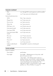
...Chassis fan PCI Express x16 Front panel control Front panel USB Front panel audio HDA header Processor Memory Power 12 V Power LAN on motherboard (LOM) Controls and Lights Front of computer: Power button Power light one, through PS/2 serial expansion card (low profile) one 25-pin connector (bidirectional) three... 240-pin connectors one 4-pin connector one 24-pin connector through RJ-45 connector on page 37). 34 Specifications - solid green for power-on state amber light - Blinking green in sleep state; Desktop Computer A solid amber light when the computer does not start indicates that...
...Chassis fan PCI Express x16 Front panel control Front panel USB Front panel audio HDA header Processor Memory Power 12 V Power LAN on motherboard (LOM) Controls and Lights Front of computer: Power button Power light one, through PS/2 serial expansion card (low profile) one 25-pin connector (bidirectional) three... 240-pin connectors one 4-pin connector one 24-pin connector through RJ-45 connector on page 37). 34 Specifications - solid green for power-on state amber light - Blinking green in sleep state; Desktop Computer A solid amber light when the computer does not start indicates that...
Setup and Quick Reference Guide
Page 35
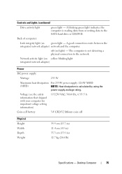
... exists between the integrated network adapter) network and the computer. A blinking green light indicates the computer is calculated by using the power supply wattage rating. Desktop Computer 35 off (no light) - Network activity light (on green light - Back of computer: Link... integrity light (on yellow blinking light integrated network adapter) Power DC power supply: Wattage 235 W Maximum heat dissipation For 235-W power supply: 126-W MHD (MHD) NOTE: Heat dissipation is reading data from or writing data to the network....
... exists between the integrated network adapter) network and the computer. A blinking green light indicates the computer is calculated by using the power supply wattage rating. Desktop Computer 35 off (no light) - Network activity light (on green light - Back of computer: Link... integrity light (on yellow blinking light integrated network adapter) Power DC power supply: Wattage 235 W Maximum heat dissipation For 235-W power supply: 126-W MHD (MHD) NOTE: Heat dissipation is reading data from or writing data to the network....
Setup and Quick Reference Guide
Page 37
...you added or removed a part before opening the cover. For additional safety best practices information, see the program documentation. IF T H E POWER LIGHT IS OFF - Using the Hardware Troubleshooter 1 Click the Windows Vista Start button , and click Help and Support. 2 Type hardware troubleshooter... Tips 37 Tips • If a device does not work, ensure that the device is not receiving power. • Reseat the power cable in a program, see www.dell.com/regulatory_compliance. NOTE: For detailed troubleshooting information, including responding to start the search. 3 In the search...
...you added or removed a part before opening the cover. For additional safety best practices information, see the program documentation. IF T H E POWER LIGHT IS OFF - Using the Hardware Troubleshooter 1 Click the Windows Vista Start button , and click Help and Support. 2 Type hardware troubleshooter... Tips 37 Tips • If a device does not work, ensure that the device is not receiving power. • Reseat the power cable in a program, see www.dell.com/regulatory_compliance. NOTE: For detailed troubleshooting information, including responding to start the search. 3 In the search...
Setup and Quick Reference Guide
Page 38
... THE COMPUTER IS NOT RESPONDING - • Ensure that the display is connected and powered on. • If the display is in your Service Manual at support.dell.com). • Ensure that the main power cable and the front panel cable are securely connected to the system board. The computer... is connected and powered on, see your Service Manual on support.dell.com. Some possible causes of interference are turned on the keyboard, move the mouse, or press the power button to resume normal operation. Press a key on . • ...
... THE COMPUTER IS NOT RESPONDING - • Ensure that the display is connected and powered on. • If the display is in your Service Manual at support.dell.com). • Ensure that the main power cable and the front panel cable are securely connected to the system board. The computer... is connected and powered on, see your Service Manual on support.dell.com. Some possible causes of interference are turned on the keyboard, move the mouse, or press the power button to resume normal operation. Press a key on . • ...
Setup and Quick Reference Guide
Page 39
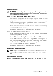
...more information about the type of memory supported by your computer, see "Specifications - Desktop Computer" on page 31. • Run the Dell Diagnostics (see "Dell Diagnostics" on page 41). IF YOU EXPERIENCE OTHER MEMORY PROBLEMS - • Reseat the memory modules to ensure that your computer. The... computer does not start up ENSURE THAT THE POWER CABLE IS FIRMLY CONNECTED TO THE COMPUTER AND TO THE ELECTRICAL OUTLET Troubleshooting ...
...more information about the type of memory supported by your computer, see "Specifications - Desktop Computer" on page 31. • Run the Dell Diagnostics (see "Dell Diagnostics" on page 41). IF YOU EXPERIENCE OTHER MEMORY PROBLEMS - • Reseat the memory modules to ensure that your computer. The... computer does not start up ENSURE THAT THE POWER CABLE IS FIRMLY CONNECTED TO THE COMPUTER AND TO THE ELECTRICAL OUTLET Troubleshooting ...
Setup and Quick Reference Guide
Page 40
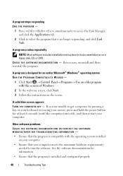
... then reinstall the program. If you are unable to get a response by pressing a key on your keyboard or moving your mouse, press and hold the power button for at least 6 seconds (until the computer turns off), and then restart your computer. • Ensure that the program is designed for information. •...
... then reinstall the program. If you are unable to get a response by pressing a key on your keyboard or moving your mouse, press and hold the power button for at least 6 seconds (until the computer turns off), and then restart your computer. • Ensure that the program is designed for information. •...
Setup and Quick Reference Guide
Page 51
... the directions. If you need to remove the computer cover, first disconnect the computer power and modem cables from a telephone at Dell Support (support.dell.com) for procedures on page 57. NOTE: Call Dell Support from all countries. When prompted by Dell's automated telephone system, enter your computer. Follow the safety instructions that the support...
... the directions. If you need to remove the computer cover, first disconnect the computer power and modem cables from a telephone at Dell Support (support.dell.com) for procedures on page 57. NOTE: Call Dell Support from all countries. When prompted by Dell's automated telephone system, enter your computer. Follow the safety instructions that the support...
Setup and Quick Reference Guide
Page 54
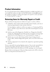
... also responsible for paying shipping expenses. For the telephone number to call for the return. 2 Include a copy of loss during shipment to Dell. You are missing any product returned, and you assume the risk of the Diagnostics Checklist (see "Diagnostics Checklist" on page 56), indicating... be refused at www.dell.com. Returning Items for credit. 4 Pack the equipment to obtain a Return Material Authorization Number, and write it clearly and prominently on ) if the return is for Warranty Repair or Credit Prepare all items being returned (power cables, software floppy disks, ...
... also responsible for paying shipping expenses. For the telephone number to call for the return. 2 Include a copy of loss during shipment to Dell. You are missing any product returned, and you assume the risk of the Diagnostics Checklist (see "Diagnostics Checklist" on page 56), indicating... be refused at www.dell.com. Returning Items for credit. 4 Pack the equipment to obtain a Return Material Authorization Number, and write it clearly and prominently on ) if the return is for Warranty Repair or Credit Prepare all items being returned (power cables, software floppy disks, ...
Setup and Quick Reference Guide
Page 59
... modem, 16 monitor, 13 network, 18 network cable, 16 power cables, 17 contacting Dell, 51, 57 D Dell contacting, 51, 57 software updates, 41 Support Utility, 41 technical support and customer service, 52 Technical Update Service, 41 Dell Diagnostics, 41 starting from the Drivers and Utilities media, 42 ...50 drivers, 43 drivers and utilities media, 49 identifying, 43 reinstalling, 43 returning to a previous version, 43 Drivers and Utilities media, 44 Dell Diagnostics, 41 drivers and utilities media, 49 E End User License Agreement (EULA), 50 ergonomics information, 50 Express Service Code, 49 F ...
... modem, 16 monitor, 13 network, 18 network cable, 16 power cables, 17 contacting Dell, 51, 57 D Dell contacting, 51, 57 software updates, 41 Support Utility, 41 technical support and customer service, 52 Technical Update Service, 41 Dell Diagnostics, 41 starting from the Drivers and Utilities media, 42 ...50 drivers, 43 drivers and utilities media, 49 identifying, 43 reinstalling, 43 returning to a previous version, 43 Drivers and Utilities media, 44 Dell Diagnostics, 41 drivers and utilities media, 49 E End User License Agreement (EULA), 50 ergonomics information, 50 Express Service Code, 49 F ...

Setup and Quick Reference Guide
Page 60
I Internet connecting, 20 setting up, 20 L license label, 50 P phone numbers, 57 power power light conditions, 37 troubleshooting, 37 problems restore to previous state, 46 M media drivers and utilities, 49 operating system, 49 memory troubleshooting, 39 N networks, 18 connecting, 18 O operating system Dell Factory Image Restore, 46 media, 47 reinstalling, 49 System Restore, 45...
I Internet connecting, 20 setting up, 20 L license label, 50 P phone numbers, 57 power power light conditions, 37 troubleshooting, 37 problems restore to previous state, 46 M media drivers and utilities, 49 operating system, 49 memory troubleshooting, 39 N networks, 18 connecting, 18 O operating system Dell Factory Image Restore, 46 media, 47 reinstalling, 49 System Restore, 45...
Setup and Quick Reference Guide
Page 61
...environmental, 30, 36 expansion bus, 26, 32 memory, 25, 32 physical, 30, 35 power, 29, 35 processor, 25, 31 system information, 25, 31 video, 26, 32 support, 51 contacting Dell, 57 DellConnect, 52 online services, 52 regional, 52 technical support and customer service, 52 support... 50 transferring information to a new computer, 21 troubleshooting, 37, 50 blue screen, 40 computer not responding, 39 Dell Diagnostics, 41 memory, 39 troubleshooting (continined) power, 37 power light conditions, 37 program crashes, 39 programs and Windows compatibility, 40 restore to previous state, 45-46 software, ...
...environmental, 30, 36 expansion bus, 26, 32 memory, 25, 32 physical, 30, 35 power, 29, 35 processor, 25, 31 system information, 25, 31 video, 26, 32 support, 51 contacting Dell, 57 DellConnect, 52 online services, 52 regional, 52 technical support and customer service, 52 support... 50 transferring information to a new computer, 21 troubleshooting, 37, 50 blue screen, 40 computer not responding, 39 Dell Diagnostics, 41 memory, 39 troubleshooting (continined) power, 37 power light conditions, 37 program crashes, 39 programs and Windows compatibility, 40 restore to previous state, 45-46 software, ...


