User Manual
Page 1
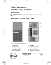
Dell OptiPlex 390/3010 Setup And Features Information About Warnings WARNING: A WARNING indicates a potential for property damage, personal injury, or death. power button 2. diagnostic lights (4) 6. optical-drive eject button 8. microphone connector 5. Front And Back View Of Mini-Tower 1. optical drive bay 3. Front And Back View Figure 1. optical drive 7. Mini-Tower - USB 2.0 connectors (2) 9. power-supply diagnostic light Regulatory Model: D04S, D07D, D12M Regulatory Type: D04S001, D07D001, D12M001 2012 - 05 hard-drive activity light 10. headphone connector 4.
Dell OptiPlex 390/3010 Setup And Features Information About Warnings WARNING: A WARNING indicates a potential for property damage, personal injury, or death. power button 2. diagnostic lights (4) 6. optical-drive eject button 8. microphone connector 5. Front And Back View Of Mini-Tower 1. optical drive bay 3. Front And Back View Figure 1. optical drive 7. Mini-Tower - USB 2.0 connectors (2) 9. power-supply diagnostic light Regulatory Model: D04S, D07D, D12M Regulatory Type: D04S001, D07D001, D12M001 2012 - 05 hard-drive activity light 10. headphone connector 4.
User Manual
Page 2
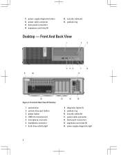
.... 11. security cable slot 11. Front And Back View Of Desktop 1. headphone connector 7. diagnostic lights (4) 9. expansion card slots (4) 14. expansion card slots (4) 15. Front And Back View Figure 2. back panel connectors 14. microphone connector 6. hard-drive activity light 8. padlock ring Desktop - optical drive 2. security cable slot 16. power cable connector 13. power...
.... 11. security cable slot 11. Front And Back View Of Desktop 1. headphone connector 7. diagnostic lights (4) 9. expansion card slots (4) 14. expansion card slots (4) 15. Front And Back View Figure 2. back panel connectors 14. microphone connector 6. hard-drive activity light 8. padlock ring Desktop - optical drive 2. security cable slot 16. power cable connector 13. power...
User Manual
Page 3
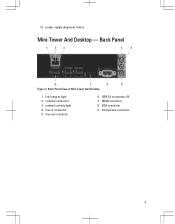
power-supply diagnostic button Mini-Tower And Desktop - link integrity light 2. network activity light 4. USB 2.0 connectors (6) 7. HDMI connector 8. network connector 3. VGA connector 9. line-out connector 6. Back Panel Figure 3. line-in connector 5. microphone connector 3 15. Back Panel View of Mini-Tower And Desktop 1.
power-supply diagnostic button Mini-Tower And Desktop - link integrity light 2. network activity light 4. USB 2.0 connectors (6) 7. HDMI connector 8. network connector 3. VGA connector 9. line-out connector 6. Back Panel Figure 3. line-in connector 5. microphone connector 3 15. Back Panel View of Mini-Tower And Desktop 1.

User Manual
Page 4
Front And Back View Figure 4. Front And Back View Of Small Form Factor 1. power button 4. security cable slot 11. Small Form Factor - hard-drive activity light 9. power cable connector 12. diagnostic lights (4) 8. padlock ring 10. power-supply diagnostic light 14. expansion card slots (2) 4 optical drive 2. power-supply diagnostic button 13. optical-drive eject button 3. USB 2.0 connectors (2) 5. microphone connector 6. headphone connector 7. back panel connectors 15.
Front And Back View Figure 4. Front And Back View Of Small Form Factor 1. power button 4. security cable slot 11. Small Form Factor - hard-drive activity light 9. power cable connector 12. diagnostic lights (4) 8. padlock ring 10. power-supply diagnostic light 14. expansion card slots (2) 4 optical drive 2. power-supply diagnostic button 13. optical-drive eject button 3. USB 2.0 connectors (2) 5. microphone connector 6. headphone connector 7. back panel connectors 15.
User Manual
Page 5
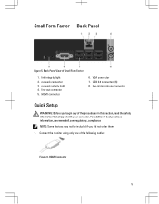
link integrity light 2. network activity light 4. USB 2.0 connectors (6) 8. HDMI Connector 5 line-out connector 5. VGA connector 7. network connector 3. line-in this section, read the safety information that shipped with your computer. Small Form Factor - Back Panel Figure 5. For additional best practices information, see www.dell.com/regulatory_compliance NOTE: Some devices may not be included if...
link integrity light 2. network activity light 4. USB 2.0 connectors (6) 8. HDMI Connector 5 line-out connector 5. VGA connector 7. network connector 3. line-in this section, read the safety information that shipped with your computer. Small Form Factor - Back Panel Figure 5. For additional best practices information, see www.dell.com/regulatory_compliance NOTE: Some devices may not be included if...
Guidebook
Page 3
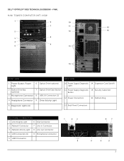
DELL™ OPTIPLEX™ 3010 TECHNICAL GUIDEBOOK -FINAL MINI TOWER COMPUTER (MT) VIEW 1 6 10 7 11 15 2 12 16 8 3 4 9 5 13 14 FRONT VIEW BACK VIEW 1 Power Button, Power Light 6 Optical Drive (optional) 2 Optical Drive Bay (optional) 7 Optical Drive Eject Button 3 Microphone Connector 8 USB 2.0 Connectors (2) 4 Headphone Connector 9 Drive Activity Light 10 Power Supply Diagnostic 14 Expansion Card Slots...
DELL™ OPTIPLEX™ 3010 TECHNICAL GUIDEBOOK -FINAL MINI TOWER COMPUTER (MT) VIEW 1 6 10 7 11 15 2 12 16 8 3 4 9 5 13 14 FRONT VIEW BACK VIEW 1 Power Button, Power Light 6 Optical Drive (optional) 2 Optical Drive Bay (optional) 7 Optical Drive Eject Button 3 Microphone Connector 8 USB 2.0 Connectors (2) 4 Headphone Connector 9 Drive Activity Light 10 Power Supply Diagnostic 14 Expansion Card Slots...
Guidebook
Page 5
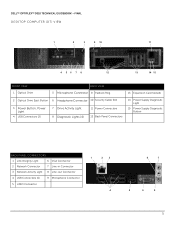
DELL™ OPTIPLEX™ 3010 TECHNICAL GUIDEBOOK -FINAL DESKTOP COMPUTER (DT) VIEW 1 2 3 9 10 11 4 56 7 8 12 13 14 15 FRONT VIEW 1 Optical Drive BACK VIEW 5 Microphone Connector 9 Padlock Ring 13 Expansion Card Slots(4) 2 Optical Drive Eject Button 6 Headphone Connector 10 Security Cable Slot 3 Power Button, Power Light 4 USB Connectors (2) 7 Drive Activity Light 8 Diagnostic Lights (4) 11 Power Connectors...
DELL™ OPTIPLEX™ 3010 TECHNICAL GUIDEBOOK -FINAL DESKTOP COMPUTER (DT) VIEW 1 2 3 9 10 11 4 56 7 8 12 13 14 15 FRONT VIEW 1 Optical Drive BACK VIEW 5 Microphone Connector 9 Padlock Ring 13 Expansion Card Slots(4) 2 Optical Drive Eject Button 6 Headphone Connector 10 Security Cable Slot 3 Power Button, Power Light 4 USB Connectors (2) 7 Drive Activity Light 8 Diagnostic Lights (4) 11 Power Connectors...
Guidebook
Page 7
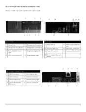
DELL™ OPTIPLEX™ 3010 TECHNICAL GUIDEBOOK -FINAL SMALL FORM FACTOR COMPUTER (SFF) VIEW 1 2 3 9 10 11 12 13 4 56 7 8 14 15 FRONT VIEW 1 Optical Drive 5 Microphone Connector 2 Optical Drive Eject Button 6 Headphone Connector 3 Power Button, Power Light 4 USB 2.0 Connectors (2) 7 Diagnostic Lights (4) 8 Drive Activity Light BACK VIEW 9 Padlock Ring 10 Security Cable Slot 11 Power Connectors 13 Power...
DELL™ OPTIPLEX™ 3010 TECHNICAL GUIDEBOOK -FINAL SMALL FORM FACTOR COMPUTER (SFF) VIEW 1 2 3 9 10 11 12 13 4 56 7 8 14 15 FRONT VIEW 1 Optical Drive 5 Microphone Connector 2 Optical Drive Eject Button 6 Headphone Connector 3 Power Button, Power Light 4 USB 2.0 Connectors (2) 7 Diagnostic Lights (4) 8 Drive Activity Light BACK VIEW 9 Padlock Ring 10 Security Cable Slot 11 Power Connectors 13 Power...

Owners Manual
Page 4
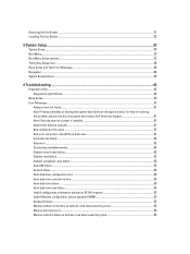
Previous attempts at booting this checkpoint and contact Dell Technical Support 51 Alert! For help in resolving this problem, please note this system have failed at address, read value expecting value 53 Memory allocation ... Enhancements...33 Timing Key Sequences...34 Beep Codes and Text Error Messages...34 Navigation...34 System Setup Options...35 4 Troubleshooting...43 Diagnostic LEDs...43 Diagnostic Light Patterns...43 Beep Codes...49 Error Messages...51 Address mark not found...51 Alert! Security override Jumper is installed...51 Attachment failed to respond...51...
Previous attempts at booting this checkpoint and contact Dell Technical Support 51 Alert! For help in resolving this problem, please note this system have failed at address, read value expecting value 53 Memory allocation ... Enhancements...33 Timing Key Sequences...34 Beep Codes and Text Error Messages...34 Navigation...34 System Setup Options...35 4 Troubleshooting...43 Diagnostic LEDs...43 Diagnostic Light Patterns...43 Beep Codes...49 Error Messages...51 Address mark not found...51 Alert! Security override Jumper is installed...51 Attachment failed to respond...51...
Owners Manual
Page 34
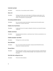
...please note this happens, a keyboard error message appears on the first method-the keyboard lights-to know the keyboard is initialized. or right-arrow key, or +/- When this checkpoint and contact Dell Technical Support. If the BIOS determine the previous boot was unsuccessful, it displays an ... field , left- To avoid this has happened: • The keyboard lights flash. • The "F2=Setup" prompt appears in plain English, along with the keys. Beep Codes and Text Error Messages The OptiPlex BIOS is capable of displaying error messages in the top right-hand corner...
...please note this happens, a keyboard error message appears on the first method-the keyboard lights-to know the keyboard is initialized. or right-arrow key, or +/- When this checkpoint and contact Dell Technical Support. If the BIOS determine the previous boot was unsuccessful, it displays an ... field , left- To avoid this has happened: • The keyboard lights flash. • The "F2=Setup" prompt appears in plain English, along with the keys. Beep Codes and Text Error Messages The OptiPlex BIOS is capable of displaying error messages in the top right-hand corner...

Owners Manual
Page 43
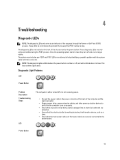
...are plugged into an electrical outlet and are securely connected to the system board. This has no longer visible. Power Button 43 Diagnostic Light Patterns LED Power Button Problem Description Troubleshooting Steps LED The computer is either turned off , and will blink when the power button is... back of the computer and the electrical outlet. • Bypass power strips, power extension cables, and other significance. NOTE: The diagnostic lights will not blink when it with the system easier and more accurate. These LEDs do not indicate the problem that caused the POST routine...
...are plugged into an electrical outlet and are securely connected to the system board. This has no longer visible. Power Button 43 Diagnostic Light Patterns LED Power Button Problem Description Troubleshooting Steps LED The computer is either turned off , and will blink when the power button is... back of the computer and the electrical outlet. • Bypass power strips, power extension cables, and other significance. NOTE: The diagnostic lights will not blink when it with the system easier and more accurate. These LEDs do not indicate the problem that caused the POST routine...
Owners Manual
Page 52
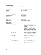
... check the file structure of paper. Decreasing available memory Description One or more memory modules may be faulty or improperly seated. If the drive access light turns on, try a different disk. General failure Description The operating system is unable to resolve the problem. Diskette drive 0 seek failure Description A cable may be...
... check the file structure of paper. Decreasing available memory Description One or more memory modules may be faulty or improperly seated. If the drive access light turns on, try a different disk. General failure Description The operating system is unable to resolve the problem. Diskette drive 0 seek failure Description A cable may be...
Owners Manual
Page 60
...5-pin connector one 3-pin connector one 24-pin and one 4-pin connector Blue light - Green light - The power cable must be connected to the hard drive. Blue light - Four lights located on the diagnostic lights, see the Service Manual at the back of the computer. System Board Connectors ...light indicates that the computer is turned on state; Solid blue light indicates power-on and is functional. blinking blue light indicates sleep state of the computer) and the electrical outlet. 60 The power supply is reading data from or writing data to the power connector (at support.dell...
...5-pin connector one 3-pin connector one 24-pin and one 4-pin connector Blue light - Green light - The power cable must be connected to the hard drive. Blue light - Four lights located on the diagnostic lights, see the Service Manual at the back of the computer. System Board Connectors ...light indicates that the computer is turned on state; Solid blue light indicates power-on and is functional. blinking blue light indicates sleep state of the computer) and the electrical outlet. 60 The power supply is reading data from or writing data to the power connector (at support.dell...

Owners Manual
Page 61
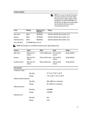
... must be defective. NOTE: Heat dissipation is within specification, the self-test LED lights up , the power supply may be connected during this test. Physical Mini-Tower Desktop...°C (-40 °F to 149 °F) 20% to 80% (non-condensing) 5% to 60 Hz, 3.6 A; Controls and Lights NOTE: You can test the health of the power system by using the power supply wattage rating. If the LED does not... light up . When the system power supply voltage is calculated by pressing the test button. Power Mini...
... must be defective. NOTE: Heat dissipation is within specification, the self-test LED lights up , the power supply may be connected during this test. Physical Mini-Tower Desktop...°C (-40 °F to 149 °F) 20% to 80% (non-condensing) 5% to 60 Hz, 3.6 A; Controls and Lights NOTE: You can test the health of the power system by using the power supply wattage rating. If the LED does not... light up . When the system power supply voltage is calculated by pressing the test button. Power Mini...
User Manual
Page 4
Previous attempts at booting this checkpoint and contact Dell Technical Support 51 Alert! For help in resolving this problem, please note this system have failed at address, read value expecting value 53 Memory allocation ... Enhancements...33 Timing Key Sequences...34 Beep Codes and Text Error Messages...34 Navigation...34 System Setup Options...35 4 Troubleshooting...43 Diagnostic LEDs...43 Diagnostic Light Patterns...43 Beep Codes...49 Error Messages...51 Address mark not found...51 Alert!
Previous attempts at booting this checkpoint and contact Dell Technical Support 51 Alert! For help in resolving this problem, please note this system have failed at address, read value expecting value 53 Memory allocation ... Enhancements...33 Timing Key Sequences...34 Beep Codes and Text Error Messages...34 Navigation...34 System Setup Options...35 4 Troubleshooting...43 Diagnostic LEDs...43 Diagnostic Light Patterns...43 Beep Codes...49 Error Messages...51 Address mark not found...51 Alert!

User Manual
Page 34
... system often passes the window of the screen during boot. To avoid this checkpoint and contact Dell Technical Support. When this happens, a keyboard error message appears on the first method-the keyboard lights-to know that this is not the first device initialized by either the keyboard or the mouse...Sequences The keyboard is the case, rely on the monitor, and you lock out the keyboard. Beep Codes and Text Error Messages The OptiPlex BIOS is capable of not requiring the technician to know the keyboard is already warmed up. Navigation The computer setup can be navigated by ...
... system often passes the window of the screen during boot. To avoid this checkpoint and contact Dell Technical Support. When this happens, a keyboard error message appears on the first method-the keyboard lights-to know that this is not the first device initialized by either the keyboard or the mouse...Sequences The keyboard is the case, rely on the monitor, and you lock out the keyboard. Beep Codes and Text Error Messages The OptiPlex BIOS is capable of not requiring the technician to know the keyboard is already warmed up. Navigation The computer setup can be navigated by ...
User Manual
Page 43
... outlet and are turned on the front of the computer and the electrical outlet. • Bypass power strips, power extension cables, and other significance. Diagnostic Light Patterns LED Power Button Problem Description Troubleshooting Steps LED The computer is either turned off , and will not blink when it is not receiving power... not indicate the problem that the main power cable and front panel cable are only active and visible during the POST process. NOTE: The diagnostic lights will blink when the power button is amber or off or is blue.
... outlet and are turned on the front of the computer and the electrical outlet. • Bypass power strips, power extension cables, and other significance. Diagnostic Light Patterns LED Power Button Problem Description Troubleshooting Steps LED The computer is either turned off , and will not blink when it is not receiving power... not indicate the problem that the main power cable and front panel cable are only active and visible during the POST process. NOTE: The diagnostic lights will blink when the power button is amber or off or is blue.

User Manual
Page 52
... failed initialization. 52 Controller has failed Description The hard drive or the associated controller is unable to carry out the command. If the drive access light turns on, try a different disk. Gate A20 failure Description One or more memory modules may not match the hardware configuration. This message is usually followed...
... failed initialization. 52 Controller has failed Description The hard drive or the associated controller is unable to carry out the command. If the drive access light turns on, try a different disk. Gate A20 failure Description One or more memory modules may not match the hardware configuration. This message is usually followed...

User Manual
Page 60
... of the computer. Blinking blue light indicates that the computer is functional. Solid amber light when the computer does not start indicates a problem with the system board. Four lights located on and is reading data from or writing data to the power connector (at support.dell.com/manuals. The power cable... must be connected to the hard drive. Blinking amber light indicates a problem with the system board or power supply. The power supply is turned on the front panel ...
... of the computer. Blinking blue light indicates that the computer is functional. Solid amber light when the computer does not start indicates a problem with the system board. Four lights located on and is reading data from or writing data to the power connector (at support.dell.com/manuals. The power cable... must be connected to the hard drive. Blinking amber light indicates a problem with the system board or power supply. The power supply is turned on the front panel ...
User Manual
Page 61
... 95% (non-condensing) 0.26 GRMS 2.2 GRMS 40 G 105 G 61 NOTE: Heat dissipation is within specification, the self-test LED lights up , the power supply may be connected during this test. If the LED does not light up . When the system power supply voltage is calculated by pressing the test button. Controls and...
... 95% (non-condensing) 0.26 GRMS 2.2 GRMS 40 G 105 G 61 NOTE: Heat dissipation is within specification, the self-test LED lights up , the power supply may be connected during this test. If the LED does not light up . When the system power supply voltage is calculated by pressing the test button. Controls and...


