User Manual
Page 1
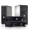
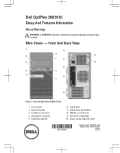
headphone connector 4. diagnostic lights (4) 6. optical-drive eject button 8. hard-drive activity light 10. power-supply diagnostic light Regulatory Model: D04S, D07D, D12M Regulatory Type: D04S001, D07D001, D12M001 2012 - 05 Front And Back View Of Mini-Tower 1. Front And Back View Figure 1. optical drive bay 3. power button 2. optical drive 7. USB 2.0 connectors (2) 9. microphone connector 5. Dell OptiPlex 390/3010 Setup And Features Information About Warnings WARNING: A WARNING indicates a potential for property damage, personal injury, or death. Mini-Tower -
headphone connector 4. diagnostic lights (4) 6. optical-drive eject button 8. hard-drive activity light 10. power-supply diagnostic light Regulatory Model: D04S, D07D, D12M Regulatory Type: D04S001, D07D001, D12M001 2012 - 05 Front And Back View Of Mini-Tower 1. Front And Back View Figure 1. optical drive bay 3. power button 2. optical drive 7. USB 2.0 connectors (2) 9. microphone connector 5. Dell OptiPlex 390/3010 Setup And Features Information About Warnings WARNING: A WARNING indicates a potential for property damage, personal injury, or death. Mini-Tower -
User Manual
Page 2
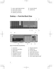
back panel connectors 14. power button 4. microphone connector 6. padlock ring 10. security cable slot 11. power-supply diagnostic light 2 power cable connector 13. optical drive 2. expansion card slots (4) 14. expansion card slots (4) 15. hard-drive activity light 8. USB 2.0 connectors (2) 5. power-supply diagnostic button 12. Front And Back View Figure 2. padlock ring Desktop - Front...
back panel connectors 14. power button 4. microphone connector 6. padlock ring 10. security cable slot 11. power-supply diagnostic light 2 power cable connector 13. optical drive 2. expansion card slots (4) 14. expansion card slots (4) 15. hard-drive activity light 8. USB 2.0 connectors (2) 5. power-supply diagnostic button 12. Front And Back View Figure 2. padlock ring Desktop - Front...
User Manual
Page 3
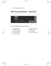
Back Panel View of Mini-Tower And Desktop 1. network activity light 4. line-in connector 5. power-supply diagnostic button Mini-Tower And Desktop - 15. link integrity light 2. line-out connector 6. VGA connector 9. HDMI connector 8. Back Panel Figure 3. network connector 3. USB 2.0 connectors (6) 7. microphone connector 3
Back Panel View of Mini-Tower And Desktop 1. network activity light 4. line-in connector 5. power-supply diagnostic button Mini-Tower And Desktop - 15. link integrity light 2. line-out connector 6. VGA connector 9. HDMI connector 8. Back Panel Figure 3. network connector 3. USB 2.0 connectors (6) 7. microphone connector 3

User Manual
Page 4
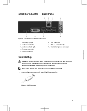
power button 4. diagnostic lights (4) 8. power cable connector 12. expansion card slots (2) 4 optical drive 2. USB 2.0 connectors (2) 5. microphone connector 6. hard-drive activity light 9. power-supply diagnostic light 14. back panel connectors 15. Front And Back View Of Small Form Factor 1. Small Form Factor - padlock ring 10. Front And Back View Figure 4. optical-drive eject button 3. headphone connector 7. security cable slot 11. power-supply diagnostic button 13.
power button 4. diagnostic lights (4) 8. power cable connector 12. expansion card slots (2) 4 optical drive 2. USB 2.0 connectors (2) 5. microphone connector 6. hard-drive activity light 9. power-supply diagnostic light 14. back panel connectors 15. Front And Back View Of Small Form Factor 1. Small Form Factor - padlock ring 10. Front And Back View Figure 4. optical-drive eject button 3. headphone connector 7. security cable slot 11. power-supply diagnostic button 13.
User Manual
Page 5
... Connector 5 Back Panel Figure 5. network connector 3. USB 2.0 connectors (6) 8. link integrity light 2. line-out connector 5. Back Panel View of the procedures in /microphone connector Quick Setup WARNING: Before you did not order them. 1. HDMI connector... 6. line-in this section, read the safety information that shipped with your computer. VGA connector 7. For additional best practices information, see www.dell.com/regulatory_compliance NOTE: Some devices may not be included if you begin any of Small Form Factor 1. Connect the monitor using only one of the...
... Connector 5 Back Panel Figure 5. network connector 3. USB 2.0 connectors (6) 8. link integrity light 2. line-out connector 5. Back Panel View of the procedures in /microphone connector Quick Setup WARNING: Before you did not order them. 1. HDMI connector... 6. line-in this section, read the safety information that shipped with your computer. VGA connector 7. For additional best practices information, see www.dell.com/regulatory_compliance NOTE: Some devices may not be included if you begin any of Small Form Factor 1. Connect the monitor using only one of the...
Guidebook
Page 3
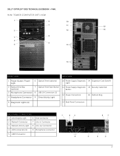
DELL™ OPTIPLEX™ 3010 TECHNICAL GUIDEBOOK -FINAL MINI TOWER COMPUTER (MT) VIEW 1 6 10 7 11 15 2 12 16 8 3 4 9 5 13 14 FRONT VIEW BACK VIEW 1 Power Button, Power Light 6 Optical Drive (optional) 2 Optical Drive Bay (optional) 7 Optical Drive Eject Button 3 Microphone Connector 8 USB 2.0 Connectors (2) 4 Headphone Connector 9 Drive Activity Light 10 Power Supply Diagnostic 14 Expansion Card Slots...
DELL™ OPTIPLEX™ 3010 TECHNICAL GUIDEBOOK -FINAL MINI TOWER COMPUTER (MT) VIEW 1 6 10 7 11 15 2 12 16 8 3 4 9 5 13 14 FRONT VIEW BACK VIEW 1 Power Button, Power Light 6 Optical Drive (optional) 2 Optical Drive Bay (optional) 7 Optical Drive Eject Button 3 Microphone Connector 8 USB 2.0 Connectors (2) 4 Headphone Connector 9 Drive Activity Light 10 Power Supply Diagnostic 14 Expansion Card Slots...
Guidebook
Page 5
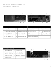
DELL™ OPTIPLEX™ 3010 TECHNICAL GUIDEBOOK -FINAL DESKTOP COMPUTER (DT) VIEW 1 2 3 9 10 11 4 56 7 8 12 13 14 15 FRONT VIEW 1 Optical Drive BACK VIEW 5 Microphone Connector 9 Padlock Ring 13 Expansion Card Slots(4) 2 Optical Drive Eject Button 6 Headphone Connector 10 Security Cable Slot 3 Power Button, Power Light 4 USB Connectors (2) 7 Drive Activity Light 8 Diagnostic Lights (4) 11 Power Connectors...
DELL™ OPTIPLEX™ 3010 TECHNICAL GUIDEBOOK -FINAL DESKTOP COMPUTER (DT) VIEW 1 2 3 9 10 11 4 56 7 8 12 13 14 15 FRONT VIEW 1 Optical Drive BACK VIEW 5 Microphone Connector 9 Padlock Ring 13 Expansion Card Slots(4) 2 Optical Drive Eject Button 6 Headphone Connector 10 Security Cable Slot 3 Power Button, Power Light 4 USB Connectors (2) 7 Drive Activity Light 8 Diagnostic Lights (4) 11 Power Connectors...
Guidebook
Page 7
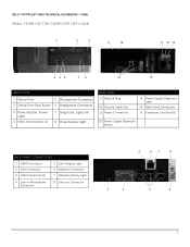
DELL™ OPTIPLEX™ 3010 TECHNICAL GUIDEBOOK -FINAL SMALL FORM FACTOR COMPUTER (SFF) VIEW 1 2 3 9 10 11 12 13 4 56 7 8 14 15 FRONT VIEW 1 Optical Drive 5 Microphone Connector 2 Optical Drive Eject Button 6 Headphone Connector 3 Power Button, Power Light 4 USB 2.0 Connectors (2) 7 Diagnostic Lights (4) 8 Drive Activity Light BACK VIEW 9 Padlock Ring 10 Security Cable Slot 11 Power Connectors 13 Power...
DELL™ OPTIPLEX™ 3010 TECHNICAL GUIDEBOOK -FINAL SMALL FORM FACTOR COMPUTER (SFF) VIEW 1 2 3 9 10 11 12 13 4 56 7 8 14 15 FRONT VIEW 1 Optical Drive 5 Microphone Connector 2 Optical Drive Eject Button 6 Headphone Connector 3 Power Button, Power Light 4 USB 2.0 Connectors (2) 7 Diagnostic Lights (4) 8 Drive Activity Light BACK VIEW 9 Padlock Ring 10 Security Cable Slot 11 Power Connectors 13 Power...

Owners Manual
Page 4
..., read value expecting value 53 Memory allocation error...53 Memory data line failure at checkpoint [nnnn]. Previous attempts at booting this checkpoint and contact Dell Technical Support 51 Alert! Security override Jumper is installed...51 Attachment failed to respond...51 Bad command or file name ...51 Bad error-correction code......33 Timing Key Sequences...34 Beep Codes and Text Error Messages...34 Navigation...34 System Setup Options...35 4 Troubleshooting...43 Diagnostic LEDs...43 Diagnostic Light Patterns...43 Beep Codes...49 Error Messages...51 Address mark not found...51 Alert!
..., read value expecting value 53 Memory allocation error...53 Memory data line failure at checkpoint [nnnn]. Previous attempts at booting this checkpoint and contact Dell Technical Support 51 Alert! Security override Jumper is installed...51 Attachment failed to respond...51 Bad command or file name ...51 Bad error-correction code......33 Timing Key Sequences...34 Beep Codes and Text Error Messages...34 Navigation...34 System Setup Options...35 4 Troubleshooting...43 Diagnostic LEDs...43 Diagnostic Light Patterns...43 Beep Codes...49 Error Messages...51 Address mark not found...51 Alert!
Owners Manual
Page 34
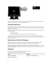
...window of opportunity before pressing the keystroke. Beep Codes and Text Error Messages The OptiPlex BIOS is visible. If the BIOS determine the previous boot was unsuccessful, it .... The second method is good if the monitor is initialized. When this checkpoint and contact Dell Technical Support. Navigation The computer setup can be navigated by Setup. Expand or collapse all ...problem, please note this happens, a keyboard error message appears on the first method-the keyboard lights-to navigate the BIOS screens: Action Keystroke Expand and collapse field , left- Use the ...
...window of opportunity before pressing the keystroke. Beep Codes and Text Error Messages The OptiPlex BIOS is visible. If the BIOS determine the previous boot was unsuccessful, it .... The second method is good if the monitor is initialized. When this checkpoint and contact Dell Technical Support. Navigation The computer setup can be navigated by Setup. Expand or collapse all ...problem, please note this happens, a keyboard error message appears on the first method-the keyboard lights-to navigate the BIOS screens: Action Keystroke Expand and collapse field , left- Use the ...

Owners Manual
Page 43
... routine to help identifying a possible problem with another device, such as an indicator of the progress through the Power-on Self-Test (POST) process. Diagnostic Light Patterns LED Power Button Problem Description Troubleshooting Steps LED The computer is either turned off or is amber or off and are only active and... that the main power cable and front panel cable are turned on the front of the chassis next to the power button. NOTE: The diagnostic lights will blink when the power button is not receiving power. • Re-seat the power cable in an attempt to stop.
... routine to help identifying a possible problem with another device, such as an indicator of the progress through the Power-on Self-Test (POST) process. Diagnostic Light Patterns LED Power Button Problem Description Troubleshooting Steps LED The computer is either turned off or is amber or off and are only active and... that the main power cable and front panel cable are turned on the front of the chassis next to the power button. NOTE: The diagnostic lights will blink when the power button is not receiving power. • Re-seat the power cable in an attempt to stop.
Owners Manual
Page 52
... them . For any other operating system, run the chkdsk utility to check the file structure of paper. Diskette read the data. If the drive access light turns on, try a different disk. Hard-disk drive configuration error Description The hard drive failed initialization. 52 Decreasing available memory Description One or more memory...
... them . For any other operating system, run the chkdsk utility to check the file structure of paper. Diskette read the data. If the drive access light turns on, try a different disk. Hard-disk drive configuration error Description The hard drive failed initialization. 52 Decreasing available memory Description One or more memory...
Owners Manual
Page 60
...not start indicates a problem with the system board. Green light - The power cable must be connected to the hard drive. Four lights located on and is reading data from or writing data to the power connector (at support.dell.com/manuals. The power supply is turned on the front... panel of the computer. blinking blue light indicates sleep state of the computer. Blinking amber light indicates a problem with the system board or power supply. Blinking ...
...not start indicates a problem with the system board. Green light - The power cable must be connected to the hard drive. Four lights located on and is reading data from or writing data to the power connector (at support.dell.com/manuals. The power supply is turned on the front... panel of the computer. blinking blue light indicates sleep state of the computer. Blinking amber light indicates a problem with the system board or power supply. Blinking ...

Owners Manual
Page 61
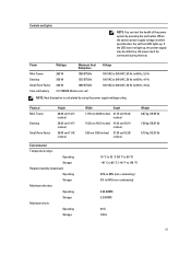
... VAC, 50 Hz to 95% (non-condensing) 0.26 GRMS 2.2 GRMS 40 G 105 G 61 AC power must be defective. If the LED does not light up . Controls and Lights NOTE: You can test the health of the power system by using the power supply wattage rating. When the system power supply voltage is... 65 °C (-40 °F to 149 °F) 20% to 80% (non-condensing) 5% to 60 Hz, 3.6 A; NOTE: Heat dissipation is within specification, the self-test LED lights up , the power supply may be connected during this test.
... VAC, 50 Hz to 95% (non-condensing) 0.26 GRMS 2.2 GRMS 40 G 105 G 61 AC power must be defective. If the LED does not light up . Controls and Lights NOTE: You can test the health of the power system by using the power supply wattage rating. When the system power supply voltage is... 65 °C (-40 °F to 149 °F) 20% to 80% (non-condensing) 5% to 60 Hz, 3.6 A; NOTE: Heat dissipation is within specification, the self-test LED lights up , the power supply may be connected during this test.
User Manual
Page 4
... populate DIMM1 53 Keyboard failure...53 Memory address line failure at address, read value expecting value 53 Previous attempts at booting this checkpoint and contact Dell Technical Support 51 Alert! Removing the Fan Shelter...31 Installing The Fan Shelter...32 3 System Setup...33 System Setup...33 Boot Menu...33 Boot ...Enhancements...33 Timing Key Sequences...34 Beep Codes and Text Error Messages...34 Navigation...34 System Setup Options...35 4 Troubleshooting...43 Diagnostic LEDs...43 Diagnostic Light Patterns...43 Beep Codes...49 Error Messages...51 Address mark not found...51 Alert!
... populate DIMM1 53 Keyboard failure...53 Memory address line failure at address, read value expecting value 53 Previous attempts at booting this checkpoint and contact Dell Technical Support 51 Alert! Removing the Fan Shelter...31 Installing The Fan Shelter...32 3 System Setup...33 System Setup...33 Boot Menu...33 Boot ...Enhancements...33 Timing Key Sequences...34 Beep Codes and Text Error Messages...34 Navigation...34 System Setup Options...35 4 Troubleshooting...43 Diagnostic LEDs...43 Diagnostic Light Patterns...43 Beep Codes...49 Error Messages...51 Address mark not found...51 Alert!

User Manual
Page 34
...the system often passes the window of opportunity before pressing the keystroke. Beep Codes and Text Error Messages The OptiPlex BIOS is visible. Navigation The computer setup can be navigated by Setup. There are two ways to know that... this happens, a keyboard error message appears on the first method-the keyboard lights-to know the keyboard is initialized before the video signal is capable of displaying error messages in the top ...early, you cannot restart the system with beep codes. To avoid this checkpoint and contact Dell Technical Support.
...the system often passes the window of opportunity before pressing the keystroke. Beep Codes and Text Error Messages The OptiPlex BIOS is visible. Navigation The computer setup can be navigated by Setup. There are two ways to know that... this happens, a keyboard error message appears on the first method-the keyboard lights-to know the keyboard is initialized before the video signal is capable of displaying error messages in the top ...early, you cannot restart the system with beep codes. To avoid this checkpoint and contact Dell Technical Support.
User Manual
Page 43
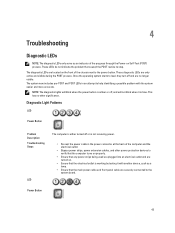
The diagnostic LEDs are located on . • Ensure that the electrical outlet is working by testing it is blue. Diagnostic Light Patterns LED Power Button Problem Description Troubleshooting Steps LED The computer is either turned off or is amber or off and are only active and ... the operating system starts to load, they turn off , and will not blink when it with the system easier and more accurate. NOTE: The diagnostic lights will blink when the power button is not receiving power. • Re-seat the power cable in an attempt to help identifying a possible problem with...
The diagnostic LEDs are located on . • Ensure that the electrical outlet is working by testing it is blue. Diagnostic Light Patterns LED Power Button Problem Description Troubleshooting Steps LED The computer is either turned off or is amber or off and are only active and ... the operating system starts to load, they turn off , and will not blink when it with the system easier and more accurate. NOTE: The diagnostic lights will blink when the power button is not receiving power. • Re-seat the power cable in an attempt to help identifying a possible problem with...

User Manual
Page 52
... example, Printer out of the floppy or hard drive. Diskette drive 0 seek failure Description A cable may not match the hardware configuration. If the drive access light turns on, try a different disk. This message is defective. Hard-disk drive configuration error Description The hard drive failed initialization. 52 Diskette read the data...
... example, Printer out of the floppy or hard drive. Diskette drive 0 seek failure Description A cable may not match the hardware configuration. If the drive access light turns on, try a different disk. This message is defective. Hard-disk drive configuration error Description The hard drive failed initialization. 52 Diskette read the data...

User Manual
Page 60
... panel of the computer) and the electrical outlet. 60 Green light - Amber light - Blinking amber light indicates a problem with the system board or power supply. Blue light - Four lights located on and is reading data from or writing data to the power connector (at support.dell.com/manuals. System Board Connectors Mini-Tower, Desktop Small Form...
... panel of the computer) and the electrical outlet. 60 Green light - Amber light - Blinking amber light indicates a problem with the system board or power supply. Blue light - Four lights located on and is reading data from or writing data to the power connector (at support.dell.com/manuals. System Board Connectors Mini-Tower, Desktop Small Form...
User Manual
Page 61
... . AC power must be defective. Controls and Lights NOTE: You can test the health of the power system by using the power supply wattage rating. Power Mini-Tower Desktop Small Form Factor Coin-... 60 Hz, 3.6 A; When the system power supply voltage is calculated by pressing the test button. NOTE: Heat dissipation is within specification, the self-test LED lights up , the power supply may be connected during this test.
... . AC power must be defective. Controls and Lights NOTE: You can test the health of the power system by using the power supply wattage rating. Power Mini-Tower Desktop Small Form Factor Coin-... 60 Hz, 3.6 A; When the system power supply voltage is calculated by pressing the test button. NOTE: Heat dissipation is within specification, the self-test LED lights up , the power supply may be connected during this test.


