Service Manual
Page 1
... your computer. Information in this document is subject to avoid the problem. Dell Latitude X300 Service Manual Dell™ Latitude™ X300 Service Manual Before You Begin Dell Diagnostics System Components Battery Memory, Modem, and Mini PCI Card Modules Keyboard Palm Rest Hard Drive Hinge Covers and Display Assembly Keyboard Tray Reserve Battery Speakers Bluetooth™ Module Cooling...
... your computer. Information in this document is subject to avoid the problem. Dell Latitude X300 Service Manual Dell™ Latitude™ X300 Service Manual Before You Begin Dell Diagnostics System Components Battery Memory, Modem, and Mini PCI Card Modules Keyboard Palm Rest Hard Drive Hinge Covers and Display Assembly Keyboard Tray Reserve Battery Speakers Bluetooth™ Module Cooling...
Service Manual
Page 14
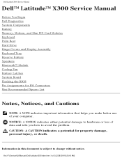
System Components: Dell Latitude X300 Service Manual 1 display 2 hinge covers (2) 3 keyboard tray 4 battery 5 cooling fan 6 hard drive 7 bottom case see Mini RSL M0270 D2589 see Mini RSL see Mini RSL 8 speakers (2) 9 reserve battery 10 Bluetooth™ module 11 system board 12 palm rest 13 keyboard 7C552 W2662 2U381 see Mini RSL G0808 5Y730 Back to Contents Page file:///F|/Service%20Manuals/Dell/Latitude/x300/system.htm (2 of 2) [2/28/2004 8:26:26 AM]
System Components: Dell Latitude X300 Service Manual 1 display 2 hinge covers (2) 3 keyboard tray 4 battery 5 cooling fan 6 hard drive 7 bottom case see Mini RSL M0270 D2589 see Mini RSL see Mini RSL 8 speakers (2) 9 reserve battery 10 Bluetooth™ module 11 system board 12 palm rest 13 keyboard 7C552 W2662 2U381 see Mini RSL G0808 5Y730 Back to Contents Page file:///F|/Service%20Manuals/Dell/Latitude/x300/system.htm (2 of 2) [2/28/2004 8:26:26 AM]
Service Manual
Page 46
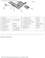
... your fingers to Contents Page Hinge Covers and Display Assembly Dell™ Latitude™ X300 Service Manual Hinge Covers Display Assembly Hinge Covers Removing the Hinge Covers CAUTION: Before you begin any of the procedures in this section, follow the safety instructions in the System Information Guide. 1. Hinge Covers and Display Assembly: Dell Latitude X300 Service Manual Back to unhook the...
... your fingers to Contents Page Hinge Covers and Display Assembly Dell™ Latitude™ X300 Service Manual Hinge Covers Display Assembly Hinge Covers Removing the Hinge Covers CAUTION: Before you begin any of the procedures in this section, follow the safety instructions in the System Information Guide. 1. Hinge Covers and Display Assembly: Dell Latitude X300 Service Manual Back to unhook the...

Service Manual
Page 47
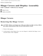
... the way (180 degrees) so that the two securing tabs on the hinge covers to the back of the computer. file:///F|/Service%20Manuals/Dell/Latitude/x300/display.htm (2 of each hinge cover are engaged in their respective slots. Ensure that it lies flat against... your work surface. 2. The left hinge cover fits over the display hinges: a. Hinge Covers and Display Assembly: Dell Latitude X300 Service Manual 1 hinge covers (2) see Mini...
... the way (180 degrees) so that the two securing tabs on the hinge covers to the back of the computer. file:///F|/Service%20Manuals/Dell/Latitude/x300/display.htm (2 of each hinge cover are engaged in their respective slots. Ensure that it lies flat against... your work surface. 2. The left hinge cover fits over the display hinges: a. Hinge Covers and Display Assembly: Dell Latitude X300 Service Manual 1 hinge covers (2) see Mini...
Service Manual
Page 48
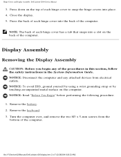
...NOTICE: Read "Before You Begin" before performing the following procedure. 1. Remove the keyboard. 3. file:///F|/Service%20Manuals/Dell/Latitude/x300/display.htm (3 of each hinge cover to snap the hinge covers into a slot on the computer. Display Assembly Removing the Display Assembly CAUTION: Before you begin any attached devices...System Information Guide. Close the display. 5. NOTICE: Disconnect the computer and any of the computer. Remove the battery. 2. Hinge Covers and Display Assembly: Dell Latitude X300 Service Manual 3. Press the back of 7) [2/28/2004 8:26:33 AM]
...NOTICE: Read "Before You Begin" before performing the following procedure. 1. Remove the keyboard. 3. file:///F|/Service%20Manuals/Dell/Latitude/x300/display.htm (3 of each hinge cover to snap the hinge covers into a slot on the computer. Display Assembly Removing the Display Assembly CAUTION: Before you begin any attached devices...System Information Guide. Close the display. 5. NOTICE: Disconnect the computer and any of the computer. Remove the battery. 2. Hinge Covers and Display Assembly: Dell Latitude X300 Service Manual 3. Press the back of 7) [2/28/2004 8:26:33 AM]

Service Manual
Page 49
Hinge Covers and Display Assembly: Dell Latitude X300 Service Manual 1 M3 x 5-mm screws (2) 7T775 4. file:///F|/Service%20Manuals/Dell/Latitude/x300/display.htm (4 of 7) [2/28/2004 8:26:33 AM] Turn the computer over and open the display 180 degrees.
Hinge Covers and Display Assembly: Dell Latitude X300 Service Manual 1 M3 x 5-mm screws (2) 7T775 4. file:///F|/Service%20Manuals/Dell/Latitude/x300/display.htm (4 of 7) [2/28/2004 8:26:33 AM] Turn the computer over and open the display 180 degrees.

Service Manual
Page 50
Hinge Covers and Display Assembly: Dell Latitude X300 Service Manual 1 M2 x 6-mm screws (2) 8T707 5. Pull the signal connector to disconnect the cables. 7. file:///F|/Service%20Manuals/Dell/Latitude/x300/display.htm (5 of the computer. 6. NOTICE: Do not pull on the top of 7) [2/28/2004 8:26:33 AM] If a tape secures the signal connector, remove it and disconnect the signal cable from the system board. 8. Disconnect the signal cable from the system board. Disconnect both the antenna connectors. Remove the two M2 x 6-mm screws near the display hinges on the signal cable.
Hinge Covers and Display Assembly: Dell Latitude X300 Service Manual 1 M2 x 6-mm screws (2) 8T707 5. Pull the signal connector to disconnect the cables. 7. file:///F|/Service%20Manuals/Dell/Latitude/x300/display.htm (5 of the computer. 6. NOTICE: Do not pull on the top of 7) [2/28/2004 8:26:33 AM] If a tape secures the signal connector, remove it and disconnect the signal cable from the system board. 8. Disconnect the signal cable from the system board. Disconnect both the antenna connectors. Remove the two M2 x 6-mm screws near the display hinges on the signal cable.
Service Manual
Page 51
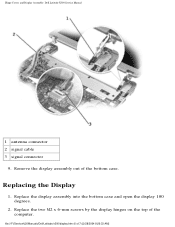
Remove the display assembly out of the computer. Replace the display assembly into the bottom case and open the display 180 degrees. 2. Replacing the Display 1. Replace the two M2 x 6-mm screws by the display hinges on the top of the bottom case. Hinge Covers and Display Assembly: Dell Latitude X300 Service Manual 1 antenna connector 2 signal cable 3 signal connector 9. file:///F|/Service%20Manuals/Dell/Latitude/x300/display.htm (6 of 7) [2/28/2004 8:26:33 AM]
Remove the display assembly out of the computer. Replace the display assembly into the bottom case and open the display 180 degrees. 2. Replacing the Display 1. Replace the two M2 x 6-mm screws by the display hinges on the top of the bottom case. Hinge Covers and Display Assembly: Dell Latitude X300 Service Manual 1 antenna connector 2 signal cable 3 signal connector 9. file:///F|/Service%20Manuals/Dell/Latitude/x300/display.htm (6 of 7) [2/28/2004 8:26:33 AM]

Service Manual
Page 52
Connect both the antenna connectors, matching the color codes. 4. Replace the two M3 x 5-mm screws from the bottom of 7) [2/28/2004 8:26:33 AM] Replace the battery. Back to Contents Page file:///F|/Service%20Manuals/Dell/Latitude/x300/display.htm (7 of the computer. 8. Hinge Covers and Display Assembly: Dell Latitude X300 Service Manual 3. If a tape secured the signal connector, replace it and connect the signal cable to the system board. 5. Close the display and turn the computer over. 7. Replace the keyboard. 9. Connect the signal cable to the system board. 6.
Connect both the antenna connectors, matching the color codes. 4. Replace the two M3 x 5-mm screws from the bottom of 7) [2/28/2004 8:26:33 AM] Replace the battery. Back to Contents Page file:///F|/Service%20Manuals/Dell/Latitude/x300/display.htm (7 of the computer. 8. Hinge Covers and Display Assembly: Dell Latitude X300 Service Manual 3. If a tape secured the signal connector, replace it and connect the signal cable to the system board. 5. Close the display and turn the computer over. 7. Replace the keyboard. 9. Connect the signal cable to the system board. 6.
Service Manual
Page 53
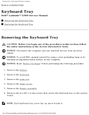
... hinge covers. 5. Remove the five M2 x 4-mm screws that secure the keyboard tray to Contents Page Keyboard Tray Dell™ Latitude™ X300 Service Manual Removing the Keyboard Tray Replacing the Keyboard Tray Removing the Keyboard Tray CAUTION: Before you begin any attached devices from electrical outlets. file:///F|/Service%20Manuals/Dell/Latitude/x300/... 3. NOTICE: Read "Before You Begin" before performing the following procedure. 1. NOTE: Each keyboard tray screw has an arrow beside it. Keyboard Tray: Dell Latitude X300 Service Manual Back to the system board.
... hinge covers. 5. Remove the five M2 x 4-mm screws that secure the keyboard tray to Contents Page Keyboard Tray Dell™ Latitude™ X300 Service Manual Removing the Keyboard Tray Replacing the Keyboard Tray Removing the Keyboard Tray CAUTION: Before you begin any attached devices from electrical outlets. file:///F|/Service%20Manuals/Dell/Latitude/x300/... 3. NOTICE: Read "Before You Begin" before performing the following procedure. 1. NOTE: Each keyboard tray screw has an arrow beside it. Keyboard Tray: Dell Latitude X300 Service Manual Back to the system board.
Service Manual
Page 69
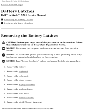
...of 3) [2/28/2004 8:26:38 AM] Remove the display assembly. 6. Remove the memory module. 9. file:///F|/Service%20Manuals/Dell/Latitude/x300/batlatch.htm (1 of the procedures in this section, follow the safety instructions in the System Information Guide. Remove the palm rest... Dell Latitude X300 Service Manual Back to Contents Page Battery Latches Dell™ Latitude™ X300 Service Manual Removing the Battery Latches Replacing the Battery Latches Removing the Battery Latches CAUTION: Before you begin any attached devices from electrical outlets. Remove the keyboard. 3. Remove the hinge...
...of 3) [2/28/2004 8:26:38 AM] Remove the display assembly. 6. Remove the memory module. 9. file:///F|/Service%20Manuals/Dell/Latitude/x300/batlatch.htm (1 of the procedures in this section, follow the safety instructions in the System Information Guide. Remove the palm rest... Dell Latitude X300 Service Manual Back to Contents Page Battery Latches Dell™ Latitude™ X300 Service Manual Removing the Battery Latches Replacing the Battery Latches Removing the Battery Latches CAUTION: Before you begin any attached devices from electrical outlets. Remove the keyboard. 3. Remove the hinge...
Service Manual
Page 72
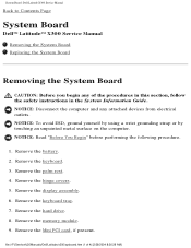
...Read "Before You Begin" before performing the following procedure. 1. Remove the hinge covers. 5. System Board: Dell Latitude X300 Service Manual Back to Contents Page System Board Dell™ Latitude™ X300 Service Manual Removing the System Board Replacing the System Board Removing the System ...you begin any attached devices from electrical outlets. Remove the battery. 2. Remove the hard drive. 8. file:///F|/Service%20Manuals/Dell/Latitude/x300/sysboard.htm (1 of the procedures in this section, follow the safety instructions in the System Information Guide. Remove the display...
...Read "Before You Begin" before performing the following procedure. 1. Remove the hinge covers. 5. System Board: Dell Latitude X300 Service Manual Back to Contents Page System Board Dell™ Latitude™ X300 Service Manual Removing the System Board Replacing the System Board Removing the System ...you begin any attached devices from electrical outlets. Remove the battery. 2. Remove the hard drive. 8. file:///F|/Service%20Manuals/Dell/Latitude/x300/sysboard.htm (1 of the procedures in this section, follow the safety instructions in the System Information Guide. Remove the display...

Service Manual
Page 88
Mini Recommended Spares List: Dell Latitude X300 Service Manual Hinges G0810 H0192 J0045 left hinge cover right hinge cover 12.1 LCD hinge up assembly Memory 3Y180 3Y182 0K963 7N020 128-MB DIMM 256-MB DIMM 512-MB DIMM 1-G DIMM Modem Y0231 56-K V2 internal modem System Board ..., 1.2 GHz (TAA compliant) Wireless 2U381 9Y200 H0294 Bluetooth™ module, internal Intel® Pro 2100 802.11b PCMCIA dummy card blank insert file:///F|/Service%20Manuals/Dell/Latitude/x300/minirsl.htm (3 of 4) [2/28/2004 8:26:41 AM]
Mini Recommended Spares List: Dell Latitude X300 Service Manual Hinges G0810 H0192 J0045 left hinge cover right hinge cover 12.1 LCD hinge up assembly Memory 3Y180 3Y182 0K963 7N020 128-MB DIMM 256-MB DIMM 512-MB DIMM 1-G DIMM Modem Y0231 56-K V2 internal modem System Board ..., 1.2 GHz (TAA compliant) Wireless 2U381 9Y200 H0294 Bluetooth™ module, internal Intel® Pro 2100 802.11b PCMCIA dummy card blank insert file:///F|/Service%20Manuals/Dell/Latitude/x300/minirsl.htm (3 of 4) [2/28/2004 8:26:41 AM]


