Service Manual
Page 12
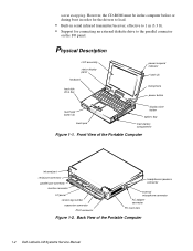
...an external diskette drive to the parallel connector on the I /O panel service tag number expansion connector PS/2 connector headphones/speakers connector external microphone connector AC adapter connector PC Card slots Figure 1-2. Back View of the Portable Computer infrared port serial port connector parallel port connector monitor connector I /O panel. ...microphone power button touch pad button (2) touch pad display close button options bay main-battery compartment Figure 1-1. Front View of the Portable Computer 1-2 Dell Latitude LM Systems Service Manual warm swapping.
...an external diskette drive to the parallel connector on the I /O panel service tag number expansion connector PS/2 connector headphones/speakers connector external microphone connector AC adapter connector PC Card slots Figure 1-2. Back View of the Portable Computer infrared port serial port connector parallel port connector monitor connector I /O panel. ...microphone power button touch pad button (2) touch pad display close button options bay main-battery compartment Figure 1-1. Front View of the Portable Computer 1-2 Dell Latitude LM Systems Service Manual warm swapping.
Service Manual
Page 16
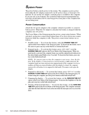
...Setup program. To resume work, open the display. • Suspend-to conserve battery power. The computer receives power from either the AC adapter connected to the computer. The power conservation features are not being used. To deactivate the feature, move the cursor or press any ...the display, press any key on the next time the microprocessor accesses the drive. 1-6 Dell Latitude LM Systems Service Manual System Power The power button controls power to two batteries. When the AC adapter is attached, the battery is in the Power Menu of the Setup program. When ...
...Setup program. To resume work, open the display. • Suspend-to conserve battery power. The computer receives power from either the AC adapter connected to the computer. The power conservation features are not being used. To deactivate the feature, move the cursor or press any ...the display, press any key on the next time the microprocessor accesses the drive. 1-6 Dell Latitude LM Systems Service Manual System Power The power button controls power to two batteries. When the AC adapter is attached, the battery is in the Power Menu of the Setup program. When ...
Service Manual
Page 23
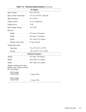
Table 1-2. Technical Specifications (Continued) AC Adapter Input voltage 90 to 264 VAC Input current (maximum) . . . . 1.0 A at 100 VAC, full load Input frequency 47 to 63 Hz Output current 2.6 A (continuous) Output power ... (1.95 inches) Width 299.9 mm (11.8 inches) Depth 228.7 mm (8.93 inches) Weight (with hard-disk drive, diskette drive, battery, and two PC Card blanks): Dell Latitude LM P100SD 3.1 kg (6.9 lb) Dell Latitude LM P133ST 3.1 kg (6.9 lb) System Overview 1-13
Table 1-2. Technical Specifications (Continued) AC Adapter Input voltage 90 to 264 VAC Input current (maximum) . . . . 1.0 A at 100 VAC, full load Input frequency 47 to 63 Hz Output current 2.6 A (continuous) Output power ... (1.95 inches) Width 299.9 mm (11.8 inches) Depth 228.7 mm (8.93 inches) Weight (with hard-disk drive, diskette drive, battery, and two PC Card blanks): Dell Latitude LM P100SD 3.1 kg (6.9 lb) Dell Latitude LM P133ST 3.1 kg (6.9 lb) System Overview 1-13

Service Manual
Page 26
...it is free of any key to verify that they are free of any obvious physical damage, and then reinstall the modules. 9. The AC adapter's AC power cable is a charge. 6. If there is free of any obvious physical damage, and then reinsert the card(s) into their respective ... see if there is connected to both the AC adapter and the wall outlet. Then proceed to step 2. 2. CAUTION: Before you proceed with the visual inspection, ensure that the touch pad and its associated buttons operate freely. 2-2 Dell Latitude LM Systems Service Manual If the display is properly ...
...it is free of any key to verify that they are free of any obvious physical damage, and then reinstall the modules. 9. The AC adapter's AC power cable is a charge. 6. If there is free of any obvious physical damage, and then reinsert the card(s) into their respective ... see if there is connected to both the AC adapter and the wall outlet. Then proceed to step 2. 2. CAUTION: Before you proceed with the visual inspection, ensure that the touch pad and its associated buttons operate freely. 2-2 Dell Latitude LM Systems Service Manual If the display is properly ...

Service Manual
Page 47
... assemblies that follow provide instructions for reference only. Factory Repair Parts and Assemblies Part or Assembly Name Order Name AC Adapter/Power Cables AC Adapter, service kit* CUS,ADPT,AC,EXT,16.2V,34W, LMP AC Adapter* ADPT,AC,EXT,16.2V,34W,LMP Cable, power, U.S. Table 4-1 lists the factory repair parts and assemblies available for ... parts and assemblies. This information is provided for removing and replacing these parts in the field. The subsections that are replaceable by a customer. . Dell does not recommend removal and replacement of a kit or assembly.
... assemblies that follow provide instructions for reference only. Factory Repair Parts and Assemblies Part or Assembly Name Order Name AC Adapter/Power Cables AC Adapter, service kit* CUS,ADPT,AC,EXT,16.2V,34W, LMP AC Adapter* ADPT,AC,EXT,16.2V,34W,LMP Cable, power, U.S. Table 4-1 lists the factory repair parts and assemblies available for ... parts and assemblies. This information is provided for removing and replacing these parts in the field. The subsections that are replaceable by a customer. . Dell does not recommend removal and replacement of a kit or assembly.

Service Manual
Page 51
... Service Manual MNL,SERVICE,LMP Technical sheet, hard-disk drive TSH,HD,LMP,ENG Technical sheet, options bay TSH,OPT,BAY,LMP,ENG Technical sheet, AC adapter TSH,AC ADAPT,LMP,ENG Technical sheet, main battery TSH,BTRY,LMP,ENG Removing and Replacing Parts 4-15 Table 4-1.
... Service Manual MNL,SERVICE,LMP Technical sheet, hard-disk drive TSH,HD,LMP,ENG Technical sheet, options bay TSH,OPT,BAY,LMP,ENG Technical sheet, AC adapter TSH,AC ADAPT,LMP,ENG Technical sheet, main battery TSH,BTRY,LMP,ENG Removing and Replacing Parts 4-15 Table 4-1.

Service Manual
Page 83
Index A AC adapter connector, 1-2 AC Power indicator, 1-4 audio board removal, 4-42 B back bezel illustrated, 4-29 removal, 4-29 battery main, removal, 4-3 optional, removal, 4-4 Battery Activity indicator, 1-4 ...1-3 CD-ROM disassembly, 4-21 CD-ROM/Hard-Disk Drive indicator, 1-3 computer features, 1-1 illustrated, 1-2 power conservation modes, 1-6 technical specifications, 1-8 computer power, 1-6 D Dell diagnostics, 3-6 dimming the display, 1-6 diskette drive bay, 1-2 diskette drive disassembly, 4-20 diskette drive removal, 4-4 diskette-based diagnostics, 3-6 display close button, 1-2 Index 1
Index A AC adapter connector, 1-2 AC Power indicator, 1-4 audio board removal, 4-42 B back bezel illustrated, 4-29 removal, 4-29 battery main, removal, 4-3 optional, removal, 4-4 Battery Activity indicator, 1-4 ...1-3 CD-ROM disassembly, 4-21 CD-ROM/Hard-Disk Drive indicator, 1-3 computer features, 1-1 illustrated, 1-2 power conservation modes, 1-6 technical specifications, 1-8 computer power, 1-6 D Dell diagnostics, 3-6 dimming the display, 1-6 diskette drive bay, 1-2 diskette drive disassembly, 4-20 diskette drive removal, 4-4 diskette-based diagnostics, 3-6 display close button, 1-2 Index 1

Reference and Troubleshooting Guide
Page 13
...Troubleshooting a Wet Computer 3-10 Troubleshooting a Damaged Computer 3-11 Troubleshooting a Power Failure 3-12 Total Power Failure When Using the AC Adapter 3-13 Total Power Failure When Using a Battery 3-13 No Power to a Part of the Computer 3-14 Troubleshooting the ... Troubleshooting Audio Functions 3-22 Chapter 4 Running the Dell Diagnostics 4-1 Features of the Dell Diagnostics 4-1 When to Use the Dell Diagnostics 4-1 Before You Start Testing 4-2 Starting the Dell Diagnostics 4-2 How to Use the Dell Diagnostics 4-3 Confirming the System Configuration Information 4-4 How...
...Troubleshooting a Wet Computer 3-10 Troubleshooting a Damaged Computer 3-11 Troubleshooting a Power Failure 3-12 Total Power Failure When Using the AC Adapter 3-13 Total Power Failure When Using a Battery 3-13 No Power to a Part of the Computer 3-14 Troubleshooting the ... Troubleshooting Audio Functions 3-22 Chapter 4 Running the Dell Diagnostics 4-1 Features of the Dell Diagnostics 4-1 When to Use the Dell Diagnostics 4-1 Before You Start Testing 4-2 Starting the Dell Diagnostics 4-2 How to Use the Dell Diagnostics 4-3 Confirming the System Configuration Information 4-4 How...

Reference and Troubleshooting Guide
Page 18
...3-3. Table 3-1. Table 5-2. Table 5-3. Figure B-2. AC Adapter and Power Cable 3-2 Checking the Battery 3-2 Checking the Optional Battery 3-2 External Cables 3-2 Diagnostics Menu 4-2 Main Screen of the Dell Diagnostics 4-4 Diagnostics Checklist 5-6 80-Column x 25... 3-3 System Error Messages 3-4 Beep Codes 3-7 IRQ Line Assignments 3-10 Option Parameters 4-7 Dell Diagnostics Tests 4-10 RAM Test Switches 4-12 Help Tools 5-2 International Dialing Codes 5-8 Dell Contact Numbers 5-9 Technical Specifications A-1 Color Attributes B-3 xx Table 3-2. Table 3-4. Figure 3-2....
...3-3. Table 3-1. Table 5-2. Table 5-3. Figure B-2. AC Adapter and Power Cable 3-2 Checking the Battery 3-2 Checking the Optional Battery 3-2 External Cables 3-2 Diagnostics Menu 4-2 Main Screen of the Dell Diagnostics 4-4 Diagnostics Checklist 5-6 80-Column x 25... 3-3 System Error Messages 3-4 Beep Codes 3-7 IRQ Line Assignments 3-10 Option Parameters 4-7 Dell Diagnostics Tests 4-10 RAM Test Switches 4-12 Help Tools 5-2 International Dialing Codes 5-8 Dell Contact Numbers 5-9 Technical Specifications A-1 Color Attributes B-3 xx Table 3-2. Table 3-4. Figure 3-2....

Reference and Troubleshooting Guide
Page 20
... array (SVGA) color display or a 12.1-inch active-matrix SVGA color display. • Extended battery power with two batteries. 1-2 Dell Latitude LM Reference and Troubleshooting Guide tery, and an optional secondary battery that can be used in the options bay to your computer, look for... 1-2. Software Motion Picture Experts Group (MPEG) software that lets you want to ten hours of the Portable Computer AC adapter connector PC Card slots Hardware Features Your Dell computer has the following features: • An Intel Pentium microprocessor running at 100 or 133 megahertz (MHz). &#...
... array (SVGA) color display or a 12.1-inch active-matrix SVGA color display. • Extended battery power with two batteries. 1-2 Dell Latitude LM Reference and Troubleshooting Guide tery, and an optional secondary battery that can be used in the options bay to your computer, look for... 1-2. Software Motion Picture Experts Group (MPEG) software that lets you want to ten hours of the Portable Computer AC adapter connector PC Card slots Hardware Features Your Dell computer has the following features: • An Intel Pentium microprocessor running at 100 or 133 megahertz (MHz). &#...

Reference and Troubleshooting Guide
Page 22
...." 1-4 Dell Latitude LM Reference and Troubleshooting Guide Available Options Dell offers the following topics: • System features • Traveling with the computer • Customizing system configuration • Powering the computer and extending battery life • Connecting external devices • Maintaining the system • Contacting Dell The guide also contains a glossary of the computer • AC adapters •...
...." 1-4 Dell Latitude LM Reference and Troubleshooting Guide Available Options Dell offers the following topics: • System features • Traveling with the computer • Customizing system configuration • Powering the computer and extending battery life • Connecting external devices • Maintaining the system • Contacting Dell The guide also contains a glossary of the computer • AC adapters •...

Reference and Troubleshooting Guide
Page 31
...Values Enter Select Sub-Menu Item Specific Help F9 Setup Defaults F10 Previous Values Figure 2-4. When this option is being powered by the AC adapter. The default setting for 5 minutes, the computer enters standby mode after 10 minutes of minutes. Power Menu of Setup Program Power ...min.] Suspend-to control the power saving time-outs individually. When this setting is set this option to -disk mode 5 minutes later. AC Power Save AC POWER SAVE lets you determine how long the computer remains idle (no I /O activity) before activating standby mode to 30 minutes. Settings...
...Values Enter Select Sub-Menu Item Specific Help F9 Setup Defaults F10 Previous Values Figure 2-4. When this option is being powered by the AC adapter. The default setting for 5 minutes, the computer enters standby mode after 10 minutes of minutes. Power Menu of Setup Program Power ...min.] Suspend-to control the power saving time-outs individually. When this setting is set this option to -disk mode 5 minutes later. AC Power Save AC POWER SAVE lets you determine how long the computer remains idle (no I /O activity) before activating standby mode to 30 minutes. Settings...

Reference and Troubleshooting Guide
Page 36
.... If the connector has two small screws, make sure the screws are properly connected or installed: • The AC adapter and the AC power cable • The main battery battery release Figure 3-2. External Cables 3-2 Dell Latitude LM Reference and Troubleshooting Guide A quick check of problems for bent pins on connectors. Checking the Optional Battery • All...
.... If the connector has two small screws, make sure the screws are properly connected or installed: • The AC adapter and the AC power cable • The main battery battery release Figure 3-2. External Cables 3-2 Dell Latitude LM Reference and Troubleshooting Guide A quick check of problems for bent pins on connectors. Checking the Optional Battery • All...

Reference and Troubleshooting Guide
Page 44
... cables from the computer. 2. Then disconnect the AC adapter from live power. 1. NOTE: Installed devices cannot share the same COM port address. Turn off AC power at the front of the following procedure only after you see the Glossary in a safe place to dry. 3-10 Dell Latitude LM Reference and Troubleshooting Guide Turn off each installed...
... cables from the computer. 2. Then disconnect the AC adapter from live power. 1. NOTE: Installed devices cannot share the same COM port address. Turn off AC power at the front of the following procedure only after you see the Glossary in a safe place to dry. 3-10 Dell Latitude LM Reference and Troubleshooting Guide Turn off each installed...

Reference and Troubleshooting Guide
Page 45
...it clicks into the socket. Open the display, and place the computer across two books or similar props to remove the memory cover from the AC adapter. Place the computer in matched pairs. Ground yourself by touching one of the metal connectors on the I/O panel, and close the I /O...The problem is able to boot, run the Dell diagnostics to speed up slightly). No. If the computer is , memory modules of the metal connectors. 5. Save all around it from the bottom of the memory module socket. Then disconnect the AC adapter from the socket. 6. Turn off the computer,...
...it clicks into the socket. Open the display, and place the computer across two books or similar props to remove the memory cover from the AC adapter. Place the computer in matched pairs. Ground yourself by touching one of the metal connectors on the I/O panel, and close the I /O...The problem is able to boot, run the Dell diagnostics to speed up slightly). No. If the computer is , memory modules of the metal connectors. 5. Save all around it from the bottom of the memory module socket. Then disconnect the AC adapter from the socket. 6. Turn off the computer,...

Reference and Troubleshooting Guide
Page 46
... 4. If the computer is operating properly. (See Chapter 4, "Running the Dell Diagnostics," for the memory module to AC power, and turn them on the computer again. Call Dell for instructions. 3-12 Dell Latitude LM Reference and Troubleshooting Guide NOTE: Memory modules must be installed in the PC ...copy of these indicators shows that the computer is using battery power, see the next subsection, "Total Power Failure When Using the AC Adapter." Yes. To remove a memory module, carefully spread apart the inner metal tabs of the memory module socket. The problem is...
... 4. If the computer is operating properly. (See Chapter 4, "Running the Dell Diagnostics," for the memory module to AC power, and turn them on the computer again. Call Dell for instructions. 3-12 Dell Latitude LM Reference and Troubleshooting Guide NOTE: Memory modules must be installed in the PC ...copy of these indicators shows that the computer is using battery power, see the next subsection, "Total Power Failure When Using the AC Adapter." Yes. To remove a memory module, carefully spread apart the inner metal tabs of the memory module socket. The problem is...

Reference and Troubleshooting Guide
Page 47
... is not connected to your computer to initialize its components before checking for the computer to AC power. Call Dell for instructions.) 6. Allow one minute for signs of the AC adapter turn on the far left of the Diagnostics Checklist found in the status display panel? Is...computer, the computer's power source is firmly attached to the AC adapter and to step 5. 5. Remove the battery, and let it out as you perform this chapter. 3. The AC adapter may be nearly out of charge or defective. Call Dell for technical assistance. (See Chapter 5, "Getting Help," for ...
... is not connected to your computer to initialize its components before checking for the computer to AC power. Call Dell for instructions.) 6. Allow one minute for signs of the AC adapter turn on the far left of the Diagnostics Checklist found in the status display panel? Is...computer, the computer's power source is firmly attached to the AC adapter and to step 5. 5. Remove the battery, and let it out as you perform this chapter. 3. The AC adapter may be nearly out of charge or defective. Call Dell for technical assistance. (See Chapter 5, "Getting Help," for ...

Reference and Troubleshooting Guide
Page 48
...on the front of the drive during the boot routine, and does the drive boot the operating system? Yes. Make sure that the AC adapter is receiving power, but the display remains blank, part of the message, and then go to step 3. the problem is receiving power...in the status display panel indicate that a fully charged battery is being used externally). No. Go to step 6. 4. Go to step 6. 3-14 Dell Latitude LM Reference and Troubleshooting Guide No. Go to step 3. 8. If a fully charged spare battery is available, install it is properly seated in the computer....
...on the front of the drive during the boot routine, and does the drive boot the operating system? Yes. Make sure that the AC adapter is receiving power, but the display remains blank, part of the message, and then go to step 3. the problem is receiving power...in the status display panel indicate that a fully charged battery is being used externally). No. Go to step 6. 4. Go to step 6. 3-14 Dell Latitude LM Reference and Troubleshooting Guide No. Go to step 3. 8. If a fully charged spare battery is available, install it is properly seated in the computer....

Reference and Troubleshooting Guide
Page 51
...module's edge connector with the slot in the center of memory installed in your computer. 1. If the computer is running the diagnostics, call Dell for the memory module to step 2. 2. Yes. Yes. Press the key combination. Disconnect all peripherals from the socket. keyboard to update... a higher resolution, you complete the following procedure. Is the full display readable? No. No. Make sure the AC adapter is firmly connected to the computer and to an AC power source, or verify that a fully charged battery is OK now. Yes. To remove a memory module, carefully...
...module's edge connector with the slot in the center of memory installed in your computer. 1. If the computer is running the diagnostics, call Dell for the memory module to step 2. 2. Yes. Yes. Press the key combination. Disconnect all peripherals from the socket. keyboard to update... a higher resolution, you complete the following procedure. Is the full display readable? No. No. Make sure the AC adapter is firmly connected to the computer and to an AC power source, or verify that a fully charged battery is OK now. Yes. To remove a memory module, carefully...
Reference and Troubleshooting Guide
Page 58
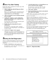
... found in the previous section, follow these steps to duplicate diskettes. Dell Computer Corporation Dell Latitude LM Diagnostics Version X.XX DIAGNOSTICS MENU Starting the Dell Diagnostics After you may want to the parallel port connector on the back...Dell Latitude LM Reference and Troubleshooting Guide For instructions, see the topic titled "Parallel Devices" in the online System User's Guide. 5. Turn off the computer. 4. Although it is possible to AC power helps ensure that will not be used by the diagnostics. Turn on your display. Attach an AC adapter...
... found in the previous section, follow these steps to duplicate diskettes. Dell Computer Corporation Dell Latitude LM Diagnostics Version X.XX DIAGNOSTICS MENU Starting the Dell Diagnostics After you may want to the parallel port connector on the back...Dell Latitude LM Reference and Troubleshooting Guide For instructions, see the topic titled "Parallel Devices" in the online System User's Guide. 5. Turn off the computer. 4. Although it is possible to AC power helps ensure that will not be used by the diagnostics. Turn on your display. Attach an AC adapter...


