Service Manual
Page 11
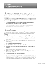
... called System Overview 1-1 The memory capacity can be increased up to the standard features found in IBM®-compatible portable computers, the Dell Latitude LM includes the following new and/or advanced features: • 8 MB of 4-, 8-, or 16-MB memory modules in the computer.... ion battery or diskette drive without turning off or rebooting the computer. For example: • The Dell Latitude LM P-100SD contains a 100-MHz Pentium micro- The individual model names within the Dell Latitude LM portable family indicate the type and operating frequency of these computers.
... called System Overview 1-1 The memory capacity can be increased up to the standard features found in IBM®-compatible portable computers, the Dell Latitude LM includes the following new and/or advanced features: • 8 MB of 4-, 8-, or 16-MB memory modules in the computer.... ion battery or diskette drive without turning off or rebooting the computer. For example: • The Dell Latitude LM P-100SD contains a 100-MHz Pentium micro- The individual model names within the Dell Latitude LM portable family indicate the type and operating frequency of these computers.
Service Manual
Page 12
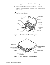
... indicator latch (2) microphone power button touch pad button (2) touch pad display close button options bay main-battery compartment Figure 1-1. Front View of the Portable Computer 1-2 Dell Latitude LM Systems Service Manual
... indicator latch (2) microphone power button touch pad button (2) touch pad display close button options bay main-battery compartment Figure 1-1. Front View of the Portable Computer 1-2 Dell Latitude LM Systems Service Manual
Service Manual
Page 14
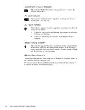
... blinking, the computer is on and the battery is no battery (main or secondary) in the computer or, if present, the battery has been discharged. 1-4 Dell Latitude LM Systems Service Manual No indicator means there is charging. Battery Activity Indicator This indicator appears when there are batteries in use or charging. Battery Status...
... blinking, the computer is on and the battery is no battery (main or secondary) in the computer or, if present, the battery has been discharged. 1-4 Dell Latitude LM Systems Service Manual No indicator means there is charging. Battery Activity Indicator This indicator appears when there are batteries in use or charging. Battery Status...
Service Manual
Page 16
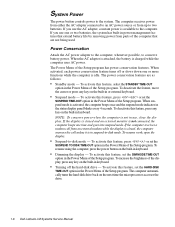
... STANDBY TIME-OUT option in keyboard. To increase the brightness of the display, press any key on the next time the microprocessor accesses the drive. 1-6 Dell Latitude LM Systems Service Manual When suspend mode is not in suspend-to two batteries. NOTE: To conserve power when the computer is activated, the computer beeps...
... STANDBY TIME-OUT option in keyboard. To increase the brightness of the display, press any key on the next time the microprocessor accesses the drive. 1-6 Dell Latitude LM Systems Service Manual When suspend mode is not in suspend-to two batteries. NOTE: To conserve power when the computer is activated, the computer beeps...

Service Manual
Page 18
... one type III card) Cards supported 3.3- Technical Specifications Table 1-2. must be installed in matched pairs Standard RAM 8 MB on system board Maximum RAM 40 MB 1-8 Dell Latitude LM Systems Service Manual
... one type III card) Cards supported 3.3- Technical Specifications Table 1-2. must be installed in matched pairs Standard RAM 8 MB on system board Maximum RAM 40 MB 1-8 Dell Latitude LM Systems Service Manual

Service Manual
Page 20
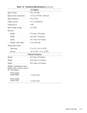
...) Maximum resolution 800 x 600 pixels; 256 colors Refresh rate (typical 70 Hz Response time (typical) . . . . . 300 ms Operating angle 0° (closed) to 135° 1-10 Dell Latitude LM Systems Service Manual
...) Maximum resolution 800 x 600 pixels; 256 colors Refresh rate (typical 70 Hz Response time (typical) . . . . . 300 ms Operating angle 0° (closed) to 135° 1-10 Dell Latitude LM Systems Service Manual

Service Manual
Page 22
... features such as charge time, operating time, and life span can vary according to the conditions under which the computer and battery are used. 1-12 Dell Latitude LM Systems Service Manual Table 1-2.
... features such as charge time, operating time, and life span can vary according to the conditions under which the computer and battery are used. 1-12 Dell Latitude LM Systems Service Manual Table 1-2.
Service Manual
Page 23
... (1.95 inches) Width 299.9 mm (11.8 inches) Depth 228.7 mm (8.93 inches) Weight (with hard-disk drive, diskette drive, battery, and two PC Card blanks): Dell Latitude LM P100SD 3.1 kg (6.9 lb) Dell Latitude LM P133ST 3.1 kg (6.9 lb) System Overview 1-13 Table 1-2.
... (1.95 inches) Width 299.9 mm (11.8 inches) Depth 228.7 mm (8.93 inches) Weight (with hard-disk drive, diskette drive, battery, and two PC Card blanks): Dell Latitude LM P100SD 3.1 kg (6.9 lb) Dell Latitude LM P133ST 3.1 kg (6.9 lb) System Overview 1-13 Table 1-2.

Service Manual
Page 24
... 2438 m (0 ft to 8,000 ft) Storage 0 m to 12,192 m (0 ft to 40,000 ft) 2 Measured with the hard-disk drive in head-parked position. 1-14 Dell Latitude LM Systems Service Manual Table 1-2.
... 2438 m (0 ft to 8,000 ft) Storage 0 m to 12,192 m (0 ft to 40,000 ft) 2 Measured with the hard-disk drive in head-parked position. 1-14 Dell Latitude LM Systems Service Manual Table 1-2.

Service Manual
Page 26
.... 5. If the display is not in the following : a. To perform a visual inspection, follow these steps: 1. Then proceed to verify that its associated buttons operate freely. 2-2 Dell Latitude LM Systems Service Manual Press the test button located on . Remove the diskette drive (if installed), verify that it is free of any obvious physical damage...
.... 5. If the display is not in the following : a. To perform a visual inspection, follow these steps: 1. Then proceed to verify that its associated buttons operate freely. 2-2 Dell Latitude LM Systems Service Manual Press the test button located on . Remove the diskette drive (if installed), verify that it is free of any obvious physical damage...

Service Manual
Page 27
... and then the computer. Turn on any attached peripherals. 2. d. Proceed to the keyboard/keypad/mouse connector on the computer's I /O panel. Dell recommends that secure the connectors at each end of the Dell Latitude LM Reference and Troubleshooting Guide. The monitor's interface cable is properly connected to the next section, "Observing the Boot Routine." 12...
... and then the computer. Turn on any attached peripherals. 2. d. Proceed to the keyboard/keypad/mouse connector on the computer's I /O panel. Dell recommends that secure the connectors at each end of the Dell Latitude LM Reference and Troubleshooting Guide. The monitor's interface cable is properly connected to the next section, "Observing the Boot Routine." 12...

Service Manual
Page 28
...the display for any of beeps that indicates an error condition. Yes. Proceed to the next section, "Eliminating Resource Conflicts." 2-4 Dell Latitude LM Systems Service Manual NOTE: The computer beeps once shortly after the boot routine starts? Yes. This beep is configured, after various ...problems or provide status information. Does the Diagnostics Menu appear on the display? No. Proceed to step 4. See "Running the Dell Diagnostics" in Chapter 3. If either of the diagnostics diskette into the diskette drive, and reboot the computer. Proceed to Table 3-1....
...the display for any of beeps that indicates an error condition. Yes. Proceed to the next section, "Eliminating Resource Conflicts." 2-4 Dell Latitude LM Systems Service Manual NOTE: The computer beeps once shortly after the boot routine starts? Yes. This beep is configured, after various ...problems or provide status information. Does the Diagnostics Menu appear on the display? No. Proceed to step 4. See "Running the Dell Diagnostics" in Chapter 3. If either of the diagnostics diskette into the diskette drive, and reboot the computer. Proceed to Table 3-1....

Service Manual
Page 32
... nnnn of low byte on memory faulty main board bus Check ROM copyright notice failure Faulty main board Interrupt mask register failure Faulty main board 3-2 Dell Latitude LM Systems Service Manual Beep Code 1-2 1-2-2-3 1-3-1-1 1-3-1-3 1-3-4-1 1-3-4-3 1-4-1-1 2-1-2-3 2-2-3-1 Table 3-1. POST Beep Codes Error Probable Causes Memory module not being properly identified or used Faulty memory module or faulty...
... nnnn of low byte on memory faulty main board bus Check ROM copyright notice failure Faulty main board Interrupt mask register failure Faulty main board 3-2 Dell Latitude LM Systems Service Manual Beep Code 1-2 1-2-2-3 1-3-1-1 1-3-1-3 1-3-4-1 1-3-4-3 1-4-1-1 2-1-2-3 2-2-3-1 Table 3-1. POST Beep Codes Error Probable Causes Memory module not being properly identified or used Faulty memory module or faulty...
Service Manual
Page 34
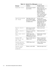
.... ule. System battery is dead-Replace and run Setup CMOS battery dead. Faulty connections. at Faulty or improperly address nnnn. seated memory mod- Faulty microprocessor. 3-4 Dell Latitude LM Systems Service Manual Operating system not installed on diskette in diskette drive. Parity check 1 nnnn Parity error in main board. bus at address nnnn. Operating...
.... ule. System battery is dead-Replace and run Setup CMOS battery dead. Faulty connections. at Faulty or improperly address nnnn. seated memory mod- Faulty microprocessor. 3-4 Dell Latitude LM Systems Service Manual Operating system not installed on diskette in diskette drive. Parity check 1 nnnn Parity error in main board. bus at address nnnn. Operating...

Service Manual
Page 36
...options or exit to the MS-DOS® prompt: • RUN QUICK TESTS - Tests the operation of the computer 3-6 Dell Latitude LM Systems Service Manual Dell recommends that users make several copies of the computer • RUN SPECIFIC TESTS - Tests the main memory • System ...Devices - Before the diagnostics loads, a program tests the portion of main memory (RAM) required for a thorough test of this diskette to Dell Latitude LM computers. This menu lets you a memory module has failed. Tests the serial communications port • Parallel Ports - Tests a network controller...
...options or exit to the MS-DOS® prompt: • RUN QUICK TESTS - Tests the operation of the computer 3-6 Dell Latitude LM Systems Service Manual Dell recommends that users make several copies of the computer • RUN SPECIFIC TESTS - Tests the main memory • System ...Devices - Before the diagnostics loads, a program tests the portion of main memory (RAM) required for a thorough test of this diskette to Dell Latitude LM computers. This menu lets you a memory module has failed. Tests the serial communications port • Parallel Ports - Tests a network controller...

Service Manual
Page 38
... aligned with its corresponding hole, and avoid overtightening. Before installing a screw, match the screw to the screw length graphics provided to check for correct length. 4-2 Dell Latitude LM Systems Service Manual Make sure that the screw is essential that the correct length screw be used when reinstalling a screw. Otherwise, hardware damage could result...
... aligned with its corresponding hole, and avoid overtightening. Before installing a screw, match the screw to the screw length graphics provided to check for correct length. 4-2 Dell Latitude LM Systems Service Manual Make sure that the screw is essential that the correct length screw be used when reinstalling a screw. Otherwise, hardware damage could result...

Service Manual
Page 40
... all the way to the left and away from the options drive bay. This feature is sometimes called hot swapping. Options Bay Lock and Latch 4-4 Dell Latitude LM Systems Service Manual Hard-Disk Drive Removal (screws HD1 and HD2 are 10 mm) 10mm 6. NOTE: The options bay allows the user to load. Slide...
... all the way to the left and away from the options drive bay. This feature is sometimes called hot swapping. Options Bay Lock and Latch 4-4 Dell Latitude LM Systems Service Manual Hard-Disk Drive Removal (screws HD1 and HD2 are 10 mm) 10mm 6. NOTE: The options bay allows the user to load. Slide...

Service Manual
Page 42
... reconnect an interface cable to disconnect a cable from a ZIF connector, follow these steps: 1. To ensure a firm connection, make sure the ZIF connector is completely closed. 4-6 Dell Latitude LM Systems Service Manual To avoid breaking the connectors, touch them . Insert a small flat-blade screwdriver under the movable part of the connector when opening or...
... reconnect an interface cable to disconnect a cable from a ZIF connector, follow these steps: 1. To ensure a firm connection, make sure the ZIF connector is completely closed. 4-6 Dell Latitude LM Systems Service Manual To avoid breaking the connectors, touch them . Insert a small flat-blade screwdriver under the movable part of the connector when opening or...

Service Manual
Page 44
LCD panel front bezel LCD panel flex cable latch hinge (2) power/suspend indicator inverter board back bezel stiffener microphone inverter board connector Figure 4-10. Exploded View-LCD Assembly 4-8 Dell Latitude LM Systems Service Manual
LCD panel front bezel LCD panel flex cable latch hinge (2) power/suspend indicator inverter board back bezel stiffener microphone inverter board connector Figure 4-10. Exploded View-LCD Assembly 4-8 Dell Latitude LM Systems Service Manual

Service Manual
Page 48
... PLSTC,LWR,FD,LMP Cable, service kit* CUST,CBL,FD,INT/EXT,LMP Connector, cable CBL,FD,INT/EXT,LMP * Customer-replaceable unit (CRU) 4-12 Dell Latitude LM Systems Service Manual
... PLSTC,LWR,FD,LMP Cable, service kit* CUST,CBL,FD,INT/EXT,LMP Connector, cable CBL,FD,INT/EXT,LMP * Customer-replaceable unit (CRU) 4-12 Dell Latitude LM Systems Service Manual


