
User Manual
Page 1
Dell Latitude E6420 ATG Setup and Features Information About Warnings WARNING: A WARNING indicates a potential for property damage, personal injury, or death. microphone 2. camera status light 5. power button 8. display 7. display release latch 3. Front view 1. wireless switch 12. Front and Back View Figure 1. eSata/USB connector 9. optical drive Regulatory Model: P15G Regulatory Type: P15G002 February 2011 camera 4. volume control buttons 11. display latch 6. USB 2.0 connectors (2) 10.
Dell Latitude E6420 ATG Setup and Features Information About Warnings WARNING: A WARNING indicates a potential for property damage, personal injury, or death. microphone 2. camera status light 5. power button 8. display 7. display release latch 3. Front view 1. wireless switch 12. Front and Back View Figure 1. eSata/USB connector 9. optical drive Regulatory Model: P15G Regulatory Type: P15G002 February 2011 camera 4. volume control buttons 11. display latch 6. USB 2.0 connectors (2) 10.

User Manual
Page 2
Secure Digital (SD) memory-card reader 16. Back view 1. power and battery status lights 5. power connector 6. cooling vents 11. Fan noise is running. ExpressCard slot 14. touchpad 19. audio connector 10. Installing the Handle Assembly 1. fingerprint reader 15. touchpad buttons (2) 18. device status lights Figure 2. USB 2.0 connector 8. trackstick buttons (3) 20. keyboard 22. HDMI connector 2. security cable slot 3. The computer turns on the fan when the computer gets hot. trackstick 21. Do not store your Dell computer in the...
Secure Digital (SD) memory-card reader 16. Back view 1. power and battery status lights 5. power connector 6. cooling vents 11. Fan noise is running. ExpressCard slot 14. touchpad 19. audio connector 10. Installing the Handle Assembly 1. fingerprint reader 15. touchpad buttons (2) 18. device status lights Figure 2. USB 2.0 connector 8. trackstick buttons (3) 20. keyboard 22. HDMI connector 2. security cable slot 3. The computer turns on the fan when the computer gets hot. trackstick 21. Do not store your Dell computer in the...

Owners Manual
Page 1
Dell Latitude E6420 and E6420 ATG Owner's Manual Regulatory Model P15G Regulatory Type P15G001, P15G002
Dell Latitude E6420 and E6420 ATG Owner's Manual Regulatory Model P15G Regulatory Type P15G001, P15G002

Owners Manual
Page 7
33 Display Panel 113 Removing the Display Panel 113 Installing the Display Panel 115 34 Display Bracket 117 Removing the Display Bracket 117 Installing the Display Bracket 117 35 Camera 119 Removing the Camera 119 Installing the Camera...120 36 Specifications 121 Technical Specifications 121 37 System Setup 129 Setup Overview...129 Entering System Setup 129 System Setup Menu...129 38 Diagnostics 141 Diagnostic LED Codes 141 Battery Status Lights...142 Device Status Lights...143 39 Contacting Dell 145 Contacting Dell...145
33 Display Panel 113 Removing the Display Panel 113 Installing the Display Panel 115 34 Display Bracket 117 Removing the Display Bracket 117 Installing the Display Bracket 117 35 Camera 119 Removing the Camera 119 Installing the Camera...120 36 Specifications 121 Technical Specifications 121 37 System Setup 129 Setup Overview...129 Entering System Setup 129 System Setup Menu...129 38 Diagnostics 141 Diagnostic LED Codes 141 Battery Status Lights...142 Device Status Lights...143 39 Contacting Dell 145 Contacting Dell...145

Owners Manual
Page 9
... service and support team. Working on Your Computer 1 Before Working Inside Your Computer Use the following conditions exist: • You have performed the steps in Working on Your Computer. • You have connectors with locking tabs; Read and follow the safety instructions that shipped with care. Hold a component such as a connector on a card. You should only perform troubleshooting and simple repairs...
... service and support team. Working on Your Computer 1 Before Working Inside Your Computer Use the following conditions exist: • You have performed the steps in Working on Your Computer. • You have connectors with locking tabs; Read and follow the safety instructions that shipped with care. Hold a component such as a connector on a card. You should only perform troubleshooting and simple repairs...

Owners Manual
Page 10
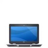
...: To avoid damaging the system board, you must remove the main battery before you service the computer. 7. Open the display. 10. Remove any installed ExpressCards or Smart Cards from the electrical outlet before opening the display. NOTE: The color of the computer. Disconnect all attached devices from the network device. 4. Press the power button to dissipate static electricity, which could harm internal components. 11. Recommended Tools The...
...: To avoid damaging the system board, you must remove the main battery before you service the computer. 7. Open the display. 10. Remove any installed ExpressCards or Smart Cards from the electrical outlet before opening the display. NOTE: The color of the computer. Disconnect all attached devices from the network device. 4. Press the power button to dissipate static electricity, which could harm internal components. 11. Recommended Tools The...
Owners Manual
Page 11
... all open programs before turning on your computer. Connect any external devices, such as a port replicator, battery slice, or media base, and replace any external devices, cards, and cables before you turn them off. Connect any telephone or network cables to the computer, use batteries designed for about 4 seconds to turn off after the operating system shutdown process is complete. 2. Shut down your operating system, press and hold the power button for other Dell computers...
... all open programs before turning on your computer. Connect any external devices, such as a port replicator, battery slice, or media base, and replace any external devices, cards, and cables before you turn them off. Connect any telephone or network cables to the computer, use batteries designed for about 4 seconds to turn off after the operating system shutdown process is complete. 2. Shut down your operating system, press and hold the power button for other Dell computers...

Owners Manual
Page 30
Attach the hard drive caddy to the hard drive. 3. Pull and remove the hard drive caddy away from the hard drive. Installing the Hard Drive 1. Slide the hard drive into the computer. 4. Follow the procedures in After working inside your computer. 30 Tighten the screw to secure the hard-drive caddy to the hard drive. 2. Install the Battery. 6. 6. Replace and tighten the screws that secure the hard drive to the computer. 5.
Attach the hard drive caddy to the hard drive. 3. Pull and remove the hard drive caddy away from the hard drive. Installing the Hard Drive 1. Slide the hard drive into the computer. 4. Follow the procedures in After working inside your computer. 30 Tighten the screw to secure the hard-drive caddy to the hard drive. 2. Install the Battery. 6. 6. Replace and tighten the screws that secure the hard drive to the computer. 5.

Owners Manual
Page 35
Remove the Secure Digital (SD) card. 6. Follow the procedures in Before Working On Your Computer 2. Use your fingertips to spread apart the securing clips on the system board by drawing the module from its connector on each end of the memory module connector until the memory module pops up. 8. Remove the memory module from the system board at a 45-degree angle. 35 Remove the base cover. 7. Remove the battery. 5. Memory Card 12 Removing the Memory Card 1. Remove the ATG Port Cover (only for E6420 ATG systems). 3. Remove the ATG Handle (only for E6420 ATG systems). 4.
Remove the Secure Digital (SD) card. 6. Follow the procedures in Before Working On Your Computer 2. Use your fingertips to spread apart the securing clips on the system board by drawing the module from its connector on each end of the memory module connector until the memory module pops up. 8. Remove the memory module from the system board at a 45-degree angle. 35 Remove the base cover. 7. Remove the battery. 5. Memory Card 12 Removing the Memory Card 1. Remove the ATG Port Cover (only for E6420 ATG systems). 3. Remove the ATG Handle (only for E6420 ATG systems). 4.

Owners Manual
Page 115
Tighten the screws securing the display panel to the display panel. 3. Install the LCD Bezel. 5. Install the Battery. 6. Connect the Low-Voltage Differential Signaling (LVDS) cable to the display assembly. 4. Installing the Display Panel 1. Follow the procedures in its original position on the display assembly. 2. Align the display panel in After Working Inside Your Computer. 115
Tighten the screws securing the display panel to the display panel. 3. Install the LCD Bezel. 5. Install the Battery. 6. Connect the Low-Voltage Differential Signaling (LVDS) cable to the display assembly. 4. Installing the Display Panel 1. Follow the procedures in its original position on the display assembly. 2. Align the display panel in After Working Inside Your Computer. 115

Owners Manual
Page 121
... the configuration of your computer, click Start → Help and Support and select the option to view information about your computer. System Information Chipset DRAM bus width Flash EPROM PCIe Gen1 bus Intel Mobile Express Series 6 chipset 64-bit SPI 32 Mbits 100 MHz Processor Types L2 cache External bus frequency • Intel Core i3 series (available only with Latitude E6420...
... the configuration of your computer, click Start → Help and Support and select the option to view information about your computer. System Information Chipset DRAM bus width Flash EPROM PCIe Gen1 bus Intel Mobile Express Series 6 chipset 64-bit SPI 32 Mbits 100 MHz Processor Types L2 cache External bus frequency • Intel Core i3 series (available only with Latitude E6420...
Owners Manual
Page 122
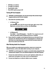
Audio Type Controller Stereo conversion Interface: Internal External Speakers Internal speaker amplifier Volume controls Video Video type Data bus: UMA Discrete Controller: UMA Latitude E6420 Latitude E6420 ATG Discrete Communications Network adapter four-channel high definition audio IDT 92HD90 24-bit (analog-to-digital and digital-to-analog) high definition audio microphone-in/stereo headphones/external speakers connector two 0.5 W (typical) per channel keyboard function keys and program menus • integrated on system board • discrete integrated video • PCI...
Audio Type Controller Stereo conversion Interface: Internal External Speakers Internal speaker amplifier Volume controls Video Video type Data bus: UMA Discrete Controller: UMA Latitude E6420 Latitude E6420 ATG Discrete Communications Network adapter four-channel high definition audio IDT 92HD90 24-bit (analog-to-digital and digital-to-analog) high definition audio microphone-in/stereo headphones/external speakers connector two 0.5 W (typical) per channel keyboard function keys and program menus • integrated on system board • discrete integrated video • PCI...

Owners Manual
Page 129
... Setup Menu The following sections describe the menu options for this keystroke will be lost. 4. Before you write down your computer. • set or change a user-selectable option such as the user password. • read the current amount of memory or set the type of hard drive installed. NOTE: The F2 prompt indicates that you use System Setup, it to display, and then press . Then, shut down the System Setup screen information...
... Setup Menu The following sections describe the menu options for this keystroke will be lost. 4. Before you write down your computer. • set or change a user-selectable option such as the user password. • read the current amount of memory or set the type of hard drive installed. NOTE: The F2 prompt indicates that you use System Setup, it to display, and then press . Then, shut down the System Setup screen information...
Owners Manual
Page 130
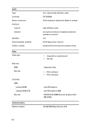
...; Device Information Battery Information Boot Sequence Displays the battery status and the type of your computer and installed devices, the items listed in which the computer attempts to configure the integrated network controller. General Option System Information Description This section lists the primary hardware features of AC adapter connected to the computer. The options are : • Disabled • Enabled 130 Allows you to find an operating system. • Diskette Drive • Internal HDD • USB...
...; Device Information Battery Information Boot Sequence Displays the battery status and the type of your computer and installed devices, the items listed in which the computer attempts to configure the integrated network controller. General Option System Information Description This section lists the primary hardware features of AC adapter connected to the computer. The options are : • Disabled • Enabled 130 Allows you to find an operating system. • Diskette Drive • Internal HDD • USB...
Owners Manual
Page 132
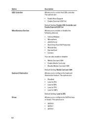
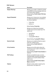
...; Enable Boot Support • Enable External USB Port Default Setting: Enable USB Controller and Enable External USB Port Allows you to enable or disable the following devices: • Internal Modem • Microphone • eSATA Ports • Hard Drive Free Fall Protection • Module Bay • ExpressCard • Camera You can also enable or disable: • Media Card and 1394 • Enable Media Card only • Disable Media Card and 1394 Default Setting: Media Card and 1394 Allows you to configure the keyboard illumination feature. Option USB Controller Miscellaneous Devices...
...; Enable Boot Support • Enable External USB Port Default Setting: Enable USB Controller and Enable External USB Port Allows you to enable or disable the following devices: • Internal Modem • Microphone • eSATA Ports • Hard Drive Free Fall Protection • Module Bay • ExpressCard • Camera You can also enable or disable: • Media Card and 1394 • Enable Media Card only • Disable Media Card and 1394 Default Setting: Media Card and 1394 Allows you to configure the keyboard illumination feature. Option USB Controller Miscellaneous Devices...
Owners Manual
Page 134
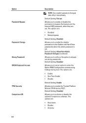
...; Reboot bypass Default Setting: Disabled Allows you to enforce the option to activate or disable the optional Computrace software. Default Setting: Disabled Allows you to enter the Option ROM Configuration screens using hotkeys during POST. Default Setting: Allow Non-Admin Password Changes is set . The options are set . The options are : • Enable • One Time Enable • Disable Default Setting: Enable Allows you to always set an option to enable the Trusted Platform Module (TPM) during boot. Option Password Bypass Password Change Strong Password OROM Keyboard...
...; Reboot bypass Default Setting: Disabled Allows you to enforce the option to activate or disable the optional Computrace software. Default Setting: Disabled Allows you to enter the Option ROM Configuration screens using hotkeys during POST. Default Setting: Allow Non-Admin Password Changes is set . The options are set . The options are : • Enable • One Time Enable • Disable Default Setting: Enable Allows you to always set an option to enable the Trusted Platform Module (TPM) during boot. Option Password Bypass Password Change Strong Password OROM Keyboard...
Owners Manual
Page 135
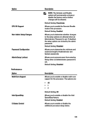
... maximum length of the processor. Default Setting: Enabled Allows you to enable the Execute Disable mode of Administrator and System passwords. Option CPU XD Support Non-Admin Setup Changes Password Configuration Admin Setup Lockout Performance Option Multi Core Support Intel SpeedStep C-States Control Description NOTE: The Activate and Disable options will permanently activate or disable the feature and no further changes will be allowed. Default Setting: Disabled Description Allows you to prevent users from entering Setup when an Administrator password is set .
... maximum length of the processor. Default Setting: Enabled Allows you to enable the Execute Disable mode of Administrator and System passwords. Option CPU XD Support Non-Admin Setup Changes Password Configuration Admin Setup Lockout Performance Option Multi Core Support Intel SpeedStep C-States Control Description NOTE: The Activate and Disable options will permanently activate or disable the feature and no further changes will be allowed. Default Setting: Disabled Description Allows you to prevent users from entering Setup when an Administrator password is set .
Owners Manual
Page 137
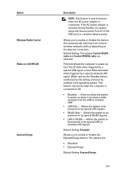
... wireless networks without depending on LAN/WLAN ExpressCharge Description NOTE: This feature is only functional when the AC power adapter is unaffected by a special wireless LAN signal. Allows the system to be powered on by special LAN signals. • WLAN Only - If the AC power adapter is connected to enable or disable the feature that automatically switches from the LAN or wireless LAN. • LAN Only - Default Setting: The options Control WLAN radio and Control...
... wireless networks without depending on LAN/WLAN ExpressCharge Description NOTE: This feature is only functional when the AC power adapter is unaffected by a special wireless LAN signal. Allows the system to be powered on by special LAN signals. • WLAN Only - If the AC power adapter is connected to enable or disable the feature that automatically switches from the LAN or wireless LAN. • LAN Only - Default Setting: The options Control WLAN radio and Control...
Owners Manual
Page 138
... Option Adapter Warnings Keypad (Embedded) Mouse/Touchpad Numlock Enable Fn Key Emulation POST HotKeys Fastboot 138 Description Allows you to enable or disable the system setup (BIOS) warning messages when you enable the sign-on screen message display indicating the keystroke sequence to access the System Setup option menu. Default Setting: Enable F12 Boot Option Menu is selected. Allows you use certain power adapters. Allows you to choose one or two methods to enable the keypad that is used to enable...
... Option Adapter Warnings Keypad (Embedded) Mouse/Touchpad Numlock Enable Fn Key Emulation POST HotKeys Fastboot 138 Description Allows you to enable or disable the system setup (BIOS) warning messages when you enable the sign-on screen message display indicating the keystroke sequence to access the System Setup option menu. Default Setting: Enable F12 Boot Option Menu is selected. Allows you use certain power adapters. Allows you to choose one or two methods to enable the keypad that is used to enable...
Owners Manual
Page 142
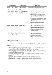
... display cable. 2. Replace the system board. Battery in charge mode with steady blue light - Replace the display panel. 3. An unauthenticated or unsupported non-Dell AC adapter is attached to an electrical outlet, the battery light operates as follows: • Alternately blinking amber light and blue light - Battery in each slot. 3. Blinki Solid Blinki Display panel ng ng error 1. Re-seat the modem. 2. Replace the video card/ system board. Battery Status Lights If the computer is already present, re-seat the module...
... display cable. 2. Replace the system board. Battery in charge mode with steady blue light - Replace the display panel. 3. An unauthenticated or unsupported non-Dell AC adapter is attached to an electrical outlet, the battery light operates as follows: • Alternately blinking amber light and blue light - Battery in each slot. 3. Blinki Solid Blinki Display panel ng ng error 1. Re-seat the modem. 2. Replace the video card/ system board. Battery Status Lights If the computer is already present, re-seat the module...


