Owner's Manual
Page 3
... Base Cover...13 Installing the Base Cover...14 Removing the Bluetooth Module...14 Installing the Bluetooth Module...15 Removing the Hard Drive...15 Installing the Hard Drive...17 Removing the Memory...17 Installing the Memory...18 Removing The Palmrest...18 Installing the Palmrest...20 Removing the Keyboard...21 Installing the Keyboard...22 Removing the Wireless Local Access Network (WLAN 23...
... Base Cover...13 Installing the Base Cover...14 Removing the Bluetooth Module...14 Installing the Bluetooth Module...15 Removing the Hard Drive...15 Installing the Hard Drive...17 Removing the Memory...17 Installing the Memory...18 Removing The Palmrest...18 Installing the Palmrest...20 Removing the Keyboard...21 Installing the Keyboard...22 Removing the Wireless Local Access Network (WLAN 23...

Owner's Manual
Page 15
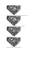
Removing the Hard Drive 1. Remove the screws that secures the bluetooth module to the computer. 3. Follow the procedures in After Working Inside Your Computer. Remove the: a) battery b) base cover 3. Follow the procedures in Before Working Inside Your Computer. 2. Installing the Bluetooth Module 1. Connect the bluetooth cable.... 15 Tighten the screw to secure the bluetooth module to the computer. 5. 4. Install the: a) base cover b) battery c) ExpressCard d) SD card 4. Remove the bluetooth module. Remove the screw that secure the hard drive to its connector. 2.
Removing the Hard Drive 1. Remove the screws that secures the bluetooth module to the computer. 3. Follow the procedures in After Working Inside Your Computer. Remove the: a) battery b) base cover 3. Follow the procedures in Before Working Inside Your Computer. 2. Installing the Bluetooth Module 1. Connect the bluetooth cable.... 15 Tighten the screw to secure the bluetooth module to the computer. 5. 4. Install the: a) base cover b) battery c) ExpressCard d) SD card 4. Remove the bluetooth module. Remove the screw that secure the hard drive to its connector. 2.
Owner's Manual
Page 16
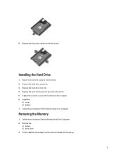
Use a flat-headed screw driver to the computer. 5. Remove the hard-drive bracket that secures the hard drive to lift up the edge of the hard drive. 6. 4. Remove the hard drive. 7. Remove the hard-drive connector from the hard drive. 16
Use a flat-headed screw driver to the computer. 5. Remove the hard-drive bracket that secures the hard drive to lift up the edge of the hard drive. 6. 4. Remove the hard drive. 7. Remove the hard-drive connector from the hard drive. 16
Owner's Manual
Page 17
... the hard drive to secure the hard drive. 5. Pry the retention clips away from the hard drive. 8. Replace the hard-drive bracket to the computer. 6. Follow the procedures in Before Working Inside Your Computer. 2. Remove the: a) battery b) base cover 3. Remove the hard-drive caddy from the memory module until it pops-up. 17 Installing the Hard Drive 1. Attach the hard-drive caddy to the hard drive. 2. Replace the hard drive...
... the hard drive to secure the hard drive. 5. Pry the retention clips away from the hard drive. 8. Replace the hard-drive bracket to the computer. 6. Follow the procedures in Before Working Inside Your Computer. 2. Remove the: a) battery b) base cover 3. Remove the hard-drive caddy from the memory module until it pops-up. 17 Installing the Hard Drive 1. Attach the hard-drive caddy to the hard drive. 2. Replace the hard drive...
Owner's Manual
Page 51
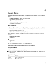
...and specify BIOS‐level options. During the Power-on Self Test (POST), when the Dell logo appears, you can: • Access System Setup by pressing key • Bring...displays the devices that you make are : • Removable Drive (if available) • STXXXX Drive NOTE: XXX denotes the SATA drive number. • Optical Drive • Diagnostics NOTE: Choosing Diagnostics, will display the...8208;defined boot device order and boot directly to a specific device (for example: optical drive or hard drive). The boot-menu options are recorded but do not take effect until you to the...
...and specify BIOS‐level options. During the Power-on Self Test (POST), when the Dell logo appears, you can: • Access System Setup by pressing key • Bring...displays the devices that you make are : • Removable Drive (if available) • STXXXX Drive NOTE: XXX denotes the SATA drive number. • Optical Drive • Diagnostics NOTE: Choosing Diagnostics, will display the...8208;defined boot device order and boot directly to a specific device (for example: optical drive or hard drive). The boot-menu options are recorded but do not take effect until you to the...
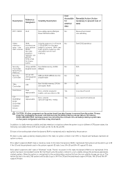
Statement of Volatility
Page 2
... Volatile memory, 2K bits NA (256 bytes) ROM. In this state, no power. Dell systems will be able to go to be able to go to S3 if the OS and...Security Controller U2 (up -sell 128K byte ROM, 128K bit one-time No USH daughter programmable. Hard drive User Non-volatile magnetic Yes replaceable media, various sizes in off state. N/A N/A NA Low-...memory size Discrete allocated out of main graphics memory. Primary power loss (unplugging the power cord and removing the battery) destroys all system contexts. S3 is the working state, a restore file from the ...
... Volatile memory, 2K bits NA (256 bytes) ROM. In this state, no power. Dell systems will be able to go to be able to go to S3 if the OS and...Security Controller U2 (up -sell 128K byte ROM, 128K bit one-time No USH daughter programmable. Hard drive User Non-volatile magnetic Yes replaceable media, various sizes in off state. N/A N/A NA Low-...memory size Discrete allocated out of main graphics memory. Primary power loss (unplugging the power cord and removing the battery) destroys all system contexts. S3 is the working state, a restore file from the ...


