View
Page 19
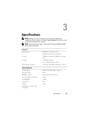
...Core 2 Duo Mobile Intel GE45 Express chipset 64 bit Dual-channel (2) 64-bit buses 32 bit 16 MB N/A 32 bit Specifications 19 Processor Processor type L1 cache L2 cache Front side bus frequency System Information System chipset Data bus width DRAM bus width...-Express used for video controllers) Intel® Core™ 2 Duo processor Intel Celeron® processor (Socket P) 32 KB per instruction, 32 KB data cache per core 1 MB (Intel Celeron) up to both the Dell™ Latitude™ E5400 and E5500 unless indicated otherwise. Specifications NOTE: Offerings may vary by region. For more...
...Core 2 Duo Mobile Intel GE45 Express chipset 64 bit Dual-channel (2) 64-bit buses 32 bit 16 MB N/A 32 bit Specifications 19 Processor Processor type L1 cache L2 cache Front side bus frequency System Information System chipset Data bus width DRAM bus width...-Express used for video controllers) Intel® Core™ 2 Duo processor Intel Celeron® processor (Socket P) 32 KB per instruction, 32 KB data cache per core 1 MB (Intel Celeron) up to both the Dell™ Latitude™ E5400 and E5500 unless indicated otherwise. Specifications NOTE: Offerings may vary by region. For more...
View
Page 34
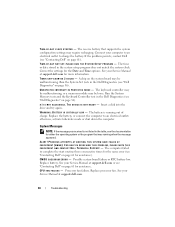
... the battery. FOR HELP IN RESOLVING THIS PROBLEM, PLEASE NOTE THIS C H E C K P O I N T A N D C O N T A C T D E L L TE C H N I L E D - Replace battery. Replace processor fan. The time or date stored in the Dell Diagnostics (see "Contacting Dell" on page 36). See your Service Manual at support.dell.com for more information. The keyboard controller may be malfunctioning, or a memory module may require...
... the battery. FOR HELP IN RESOLVING THIS PROBLEM, PLEASE NOTE THIS C H E C K P O I N T A N D C O N T A C T D E L L TE C H N I L E D - Replace battery. Replace processor fan. The time or date stored in the Dell Diagnostics (see "Contacting Dell" on page 36). See your Service Manual at support.dell.com for more information. The keyboard controller may be malfunctioning, or a memory module may require...
View
Page 39
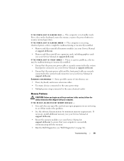
...to the same power strip • Multiple power strips connected to see if that the processor power cable is a power problem, a device may be malfunctioning or incorrectly installed. ...• Remove and then reinstall all memory modules (see your Service Manual at support.dell.com). • Remove and then reinstall any of interference are securely connected to resume normal operation. I F T H E P O W E R L I G H T I S B L I N K I S S T E A D Y A M B E R - ELIMINATE INTERFERENCE - I F T H E P O W E R L...
...to the same power strip • Multiple power strips connected to see if that the processor power cable is a power problem, a device may be malfunctioning or incorrectly installed. ...• Remove and then reinstall all memory modules (see your Service Manual at support.dell.com). • Remove and then reinstall any of interference are securely connected to resume normal operation. I F T H E P O W E R L I G H T I S B L I N K I S S T E A D Y A M B E R - ELIMINATE INTERFERENCE - I F T H E P O W E R L...
View
Page 65
...communications, 21 display, 22 environmental, 26 keyboard, 23 memory, 20 physical, 25 ports and connectors, 20 processor, 19 system information, 19 touch pad, 23 video, 21 support contacting Dell, 61 information, 54 System Restore, 48 enabling, 50 T telephone numbers, 61 transferring information to a new... computer, 15 troubleshooting, 54 blue screen, 41 computer not responding, 40 Dell Diagnostics, 36 error messages, 29 memory, 39 power, 38 power light conditions, 38 program crashes, 40 programs and Windows compatibility, 41...
...communications, 21 display, 22 environmental, 26 keyboard, 23 memory, 20 physical, 25 ports and connectors, 20 processor, 19 system information, 19 touch pad, 23 video, 21 support contacting Dell, 61 information, 54 System Restore, 48 enabling, 50 T telephone numbers, 61 transferring information to a new... computer, 15 troubleshooting, 54 blue screen, 41 computer not responding, 40 Dell Diagnostics, 36 error messages, 29 memory, 39 power, 38 power light conditions, 38 program crashes, 40 programs and Windows compatibility, 41...
Technical Guide
Page 8
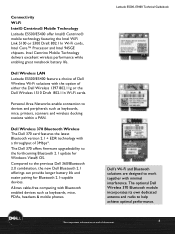
...are designed to work together with the option of document 8 Dell Wireless LAN Latitude E5500/E5400 feature a choice of 3Mbps*. Personal Area Networks enable connection to the previous Dell 360/Bluetooth 2.0 combination, the new Dell Bluetooth 2.1 offerings can provide longer battery life and easier ...Dell Wireless Wi-Fi solutions with minimal interference. Connectivity Wi-Fi Intel® Centrino® Mobile Technology Latitude E5500/E5400 offer Intel® Centrino® mobile technology featuring the Intel WiFi Link 5100 or 5300 Draft 802.11n Wi-Fi cards, Intel Core™ Processor...
...are designed to work together with the option of document 8 Dell Wireless LAN Latitude E5500/E5400 feature a choice of 3Mbps*. Personal Area Networks enable connection to the previous Dell 360/Bluetooth 2.0 combination, the new Dell Bluetooth 2.1 offerings can provide longer battery life and easier ...Dell Wireless Wi-Fi solutions with minimal interference. Connectivity Wi-Fi Intel® Centrino® Mobile Technology Latitude E5500/E5400 offer Intel® Centrino® mobile technology featuring the Intel WiFi Link 5100 or 5300 Draft 802.11n Wi-Fi cards, Intel Core™ Processor...
Technical Guide
Page 29
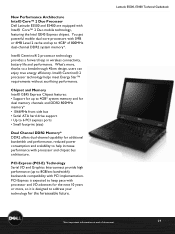
... expected to address your technology for the foreseeable future. PCI-Express is designed to keep pace with PCI implementation. Intel® Centrino® 2 processor technology provides a forward leap in wireless connectivity, battery life and performance. PCI-Express (PCI-E) Technology Serial I /O advances for additional bandwidth and ...174; Core™ 2 Duo mobile technology, featuring the Intel GE45 Express chipset. New Performance Architecture Intel® Core™ 2 Duo Processor Dell Latitude E5500 and E5400 are equipped with processor and chipset bus architecture.
... expected to address your technology for the foreseeable future. PCI-Express is designed to keep pace with PCI implementation. Intel® Centrino® 2 processor technology provides a forward leap in wireless connectivity, battery life and performance. PCI-Express (PCI-E) Technology Serial I /O advances for additional bandwidth and ...174; Core™ 2 Duo mobile technology, featuring the Intel GE45 Express chipset. New Performance Architecture Intel® Core™ 2 Duo Processor Dell Latitude E5500 and E5400 are equipped with processor and chipset bus architecture.
Technical Guide
Page 35
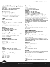
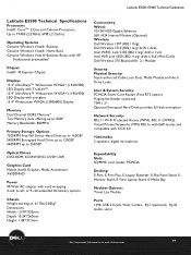
...) 802.1x with EAP modes and compatible with GPS and service from AT&T (US) and Vodafone (select countries in Europe) Dell Wireless 5720 Mobile Broadband* (EVDO Rev A) MiniCard with CCX 4.0 Multimedia 2 speakers, digital microphone Expandability Slots: SD/MMC card .../1000 Gigabit Ethernet 56K v924 Internal Modem (Optional) Wireless: Dell Wireless 1397 (802.11b/g); LaLtaittuitduedeE5E550500,0E, 5E4504000TeTcehcnhincaiclaGl Guiudiedbeobookok Latitude E5400 Technical Specifications Processors Intel® CoreTM 2 Duo and Celeron Processors Up to T9400 (2.53GHz, 6MB L2 Cache) Operating Systems ...
...) 802.1x with EAP modes and compatible with GPS and service from AT&T (US) and Vodafone (select countries in Europe) Dell Wireless 5720 Mobile Broadband* (EVDO Rev A) MiniCard with CCX 4.0 Multimedia 2 speakers, digital microphone Expandability Slots: SD/MMC card .../1000 Gigabit Ethernet 56K v924 Internal Modem (Optional) Wireless: Dell Wireless 1397 (802.11b/g); LaLtaittuitduedeE5E550500,0E, 5E4504000TeTcehcnhincaiclaGl Guiudiedbeobookok Latitude E5400 Technical Specifications Processors Intel® CoreTM 2 Duo and Celeron Processors Up to T9400 (2.53GHz, 6MB L2 Cache) Operating Systems ...
Technical Guide
Page 39
Dell Wireless 1510 (802.11a/g/ draft n 2x2); PCMCIA Docking: E-Port, E-Port Plus, E-Legacy Extender, E-Flat Panel Stand, EMonitor Stand, E-View Laptop Stand, E-Media Bay ... Link 5300 (802.11a/g/ draft n 3x3) Mini-Cards Dell Wireless 370 Bluetooth® 2.1 Module Security Physical Security: Steel-reinforced Cable Lock Slots, Media Module and Hard Drive Locks. LaLtaittuitduedeE5E550500,0E, 5E4504000TeTcehcnhincaiclaGl Guiudiedbeobookok Latitude E5500 Technical Specifications Processors Intel® CoreTM 2 Duo and Celeron Processors Up to T9400 (2.53GHz, 6MB L2 Cache) Operating Systems...
Dell Wireless 1510 (802.11a/g/ draft n 2x2); PCMCIA Docking: E-Port, E-Port Plus, E-Legacy Extender, E-Flat Panel Stand, EMonitor Stand, E-View Laptop Stand, E-Media Bay ... Link 5300 (802.11a/g/ draft n 3x3) Mini-Cards Dell Wireless 370 Bluetooth® 2.1 Module Security Physical Security: Steel-reinforced Cable Lock Slots, Media Module and Hard Drive Locks. LaLtaittuitduedeE5E550500,0E, 5E4504000TeTcehcnhincaiclaGl Guiudiedbeobookok Latitude E5500 Technical Specifications Processors Intel® CoreTM 2 Duo and Celeron Processors Up to T9400 (2.53GHz, 6MB L2 Cache) Operating Systems...
Technical Guide
Page 41
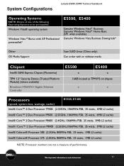
System Configurations Latitude E5500, E5400LaTtietucdheniEc5a5l 0G0u, Eid5e4b0o0oTkechnical Guidebook Operating Systems NOTE: Choice of one of document 41 Windows Vista® operating system Windows Vista ® Bonus with XP Professional preinstalled* E5500, E5400 Genuine Windows Vista® ...Platform Module) (where available) Broadcom 5756/5761 Gigabit Ethernet Controller E5500 E5400 x x 16KB located at TPM1P2 on chipset x x Processors (speed, system bus, wattage, cache) E5500, E5400 Intel® Core™ 2 Duo Processor T9400 (2.53GHz, 1066MHz FSB, 35 watts, 6MB L2 cache...
System Configurations Latitude E5500, E5400LaTtietucdheniEc5a5l 0G0u, Eid5e4b0o0oTkechnical Guidebook Operating Systems NOTE: Choice of one of document 41 Windows Vista® operating system Windows Vista ® Bonus with XP Professional preinstalled* E5500, E5400 Genuine Windows Vista® ...Platform Module) (where available) Broadcom 5756/5761 Gigabit Ethernet Controller E5500 E5400 x x 16KB located at TPM1P2 on chipset x x Processors (speed, system bus, wattage, cache) E5500, E5400 Intel® Core™ 2 Duo Processor T9400 (2.53GHz, 1066MHz FSB, 35 watts, 6MB L2 cache...
Service Manual
Page 1
... to either potential damage to hardware or loss of data and tells you make better use of your computer. Dell™ Latitude™ E5400 and E5500 Service Manual Troubleshooting Working on Your Computer Bottom of the Base Assembly Hard Drive Wireless Local Area Network (WLAN)... Card Modem Card Fan Processor Heat Sink Processor Module Memory Hinge Cover Keyboard LED Dashboard Display Optical Drive Palm Rest System Board Assembly...
... to either potential damage to hardware or loss of data and tells you make better use of your computer. Dell™ Latitude™ E5400 and E5500 Service Manual Troubleshooting Working on Your Computer Bottom of the Base Assembly Hard Drive Wireless Local Area Network (WLAN)... Card Modem Card Fan Processor Heat Sink Processor Module Memory Hinge Cover Keyboard LED Dashboard Display Optical Drive Palm Rest System Board Assembly...
Service Manual
Page 4
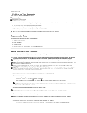
... assumes that the connectors are correctly oriented and aligned to avoid damage to Contents Page Working on Your Computer Dell™ Latitude™ E5400 and E5500 Service Manual Recommended Tools Before Working on Your Computer After Working on Your Computer Use the following safety guidelines ...any installed cards before you cannot shut down your computer. l When replacing a component, you begin any installed cards, such as a processor by its metal mounting bracket. NOTICE: To avoid electrostatic discharge, ground yourself by using the operating system, press and hold the power...
... assumes that the connectors are correctly oriented and aligned to avoid damage to Contents Page Working on Your Computer Dell™ Latitude™ E5400 and E5500 Service Manual Recommended Tools Before Working on Your Computer After Working on Your Computer Use the following safety guidelines ...any installed cards before you cannot shut down your computer. l When replacing a component, you begin any installed cards, such as a processor by its metal mounting bracket. NOTICE: To avoid electrostatic discharge, ground yourself by using the operating system, press and hold the power...
Service Manual
Page 10
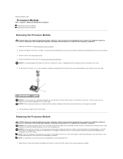
...socket cam screw 2 ZIF socket NOTICE: To ensure maximum cooling for the processor, do not touch the heat transfer areas on www.dell.com at : www.dell.com/regulatory_compliance. 1. Lift the processor module from the ZIF socket. Follow the instructions in the ZIF socket ...cam screw to the microprocessor and ZIF socket. Back to Contents Page Processor Module Dell™ Latitude™ E5400 and E5500 Service Manual Removing the Processor Module Replacing the Processor Module Removing the Processor Module CAUTION: Before you begin the following procedure, follow the safety ...
...socket cam screw 2 ZIF socket NOTICE: To ensure maximum cooling for the processor, do not touch the heat transfer areas on www.dell.com at : www.dell.com/regulatory_compliance. 1. Lift the processor module from the ZIF socket. Follow the instructions in the ZIF socket ...cam screw to the microprocessor and ZIF socket. Back to Contents Page Processor Module Dell™ Latitude™ E5400 and E5500 Service Manual Removing the Processor Module Replacing the Processor Module Removing the Processor Module CAUTION: Before you begin the following procedure, follow the safety ...
Service Manual
Page 11
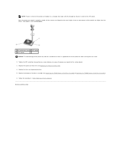
...Tighten the ZIF socket by turning the cam screw clockwise to secure the processor module to Contents Page Replace the bottom of the base assembly (see Replacing the E5400 Bottom of the Base Assembly or Replacing the E5500 Bottom of the Base Assembly). 6. Follow the procedures in After Working on... the pin-1 corner of the ZIF socket. Back to the system board. 3. When the processor module is properly seated, all four corners are higher than...
...Tighten the ZIF socket by turning the cam screw clockwise to secure the processor module to Contents Page Replace the bottom of the base assembly (see Replacing the E5400 Bottom of the Base Assembly or Replacing the E5500 Bottom of the Base Assembly). 6. Follow the procedures in After Working on... the pin-1 corner of the ZIF socket. Back to the system board. 3. When the processor module is properly seated, all four corners are higher than...
Service Manual
Page 12
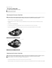
... closest to the front of the Base Assembly). 3. Tighten the four numbered Back to Contents Page Processor Heat Sink Dell™ Latitude™ E5400 and E5500 Service Manual Removing the Processor Heat Sink Replacing the Processor Heat Sink Removing the Processor Heat Sink CAUTION: Before you begin the following procedure, follow the safety instructions that shipped with...
... closest to the front of the Base Assembly). 3. Tighten the four numbered Back to Contents Page Processor Heat Sink Dell™ Latitude™ E5400 and E5500 Service Manual Removing the Processor Heat Sink Replacing the Processor Heat Sink Removing the Processor Heat Sink CAUTION: Before you begin the following procedure, follow the safety instructions that shipped with...
Service Manual
Page 34
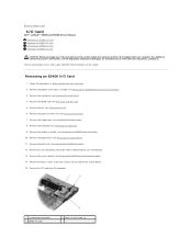
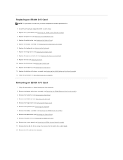
For additional safety best practices information, see Processor Heat Sink). 7. Remove the processor heat sink (see the Regulatory Compliance Homepage on Your Computer. 2. Remove the I/O card from the computer. 1 system board connector 3 E5400 I /O card... Remove the system board (see Removing the Fan). 6. Back to Contents Page I/O Card Dell™ Latitude™ E5400 and E5500 Service Manual Removing an E5400 I/O Card Replacing an E5400 I/O Card Removing an E5500 I/O Card Replacing an E5500 I/O Card CAUTION: Before you begin any of the Base Assembly). 3. Remove the bottom of...
For additional safety best practices information, see Processor Heat Sink). 7. Remove the processor heat sink (see the Regulatory Compliance Homepage on Your Computer. 2. Remove the I/O card from the computer. 1 system board connector 3 E5400 I /O card... Remove the system board (see Removing the Fan). 6. Back to Contents Page I/O Card Dell™ Latitude™ E5400 and E5500 Service Manual Removing an E5400 I/O Card Replacing an E5400 I/O Card Removing an E5500 I/O Card Replacing an E5500 I/O Card CAUTION: Before you begin any of the Base Assembly). 3. Remove the bottom of...
Service Manual
Page 35
Replace the optical drive (see Replacing the Processor Heat Sink). 9. Replace the processor heat sink (see Replacing the Optical Drive). 5. Remove the hard drive (see Replacing the E5400 System Board Assembly) 3. Remove the I /O Card 1. Replace the system ... E5400 Bottom of the base assembly (see Replacing the Hard Drive). 12. Remove the bottom of the Base Assembly). 3. Remove the keyboard (see Removing the E5500 Palm Rest). 10. Remove the palm rest (see Removing the Keyboard). 7. Follow the procedures in Before Working on Your Computer. Replacing an E5400 I /O card...
Replace the optical drive (see Replacing the Processor Heat Sink). 9. Replace the processor heat sink (see Replacing the Optical Drive). 5. Remove the hard drive (see Replacing the E5400 System Board Assembly) 3. Remove the I /O Card 1. Replace the system ... E5400 Bottom of the base assembly (see Replacing the Hard Drive). 12. Remove the bottom of the Base Assembly). 3. Remove the keyboard (see Removing the E5500 Palm Rest). 10. Remove the palm rest (see Removing the Keyboard). 7. Follow the procedures in Before Working on Your Computer. Replacing an E5400 I /O card...

Service Manual
Page 40
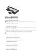
... at : www.dell.com/regulatory_compliance. 1. Replace the palm rest (see Removing the Keyboard). 4. Remove the keyboard (see Replacing the E5400 Palm Rest). 6. Place the LED Dashboard cable in After Working on Your Computer. 2. Replace the processor heat sink (see Replacing the E5400 ... Compliance Homepage on the tab near cable's connector. 1 LED Dashboard cable 2 LED Dashboard cable connector 3 LED Dashboard Replacing the E5500 LED Dashboard CAUTION: Before you begin any of the procedures in this section, follow the safety instructions that shipped with your computer...
... at : www.dell.com/regulatory_compliance. 1. Replace the palm rest (see Removing the Keyboard). 4. Remove the keyboard (see Replacing the E5400 Palm Rest). 6. Place the LED Dashboard cable in After Working on Your Computer. 2. Replace the processor heat sink (see Replacing the E5400 ... Compliance Homepage on the tab near cable's connector. 1 LED Dashboard cable 2 LED Dashboard cable connector 3 LED Dashboard Replacing the E5500 LED Dashboard CAUTION: Before you begin any of the procedures in this section, follow the safety instructions that shipped with your computer...
Service Manual
Page 49
...from the bottom of the computer, carefully remove the speaker and touchpad wires from the computer. Replace the display assembly (see Replacing the Processor Heat Sink). 11. Replace the hinge cover (see Replacing a WLAN Card). Be sure that shipped with the computer base and gently snap... into place. 3. Replace the 13 M2.5 x 8-mm screws to the system board 2. Replace the three M2 x 3-mm screws at : www.dell.com/regulatory_compliance. Replacing the E5400 Palm Rest CAUTION: Before you have completed the removal procedure first. 1. Replace the WLAN card (see Replacing the Hinge ...
...from the bottom of the computer, carefully remove the speaker and touchpad wires from the computer. Replace the display assembly (see Replacing the Processor Heat Sink). 11. Replace the hinge cover (see Replacing a WLAN Card). Be sure that shipped with the computer base and gently snap... into place. 3. Replace the 13 M2.5 x 8-mm screws to the system board 2. Replace the three M2 x 3-mm screws at : www.dell.com/regulatory_compliance. Replacing the E5400 Palm Rest CAUTION: Before you have completed the removal procedure first. 1. Replace the WLAN card (see Replacing the Hinge ...
Service Manual
Page 53
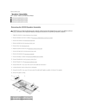
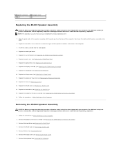
... 1 left speaker assemblies to Contents Page Speaker Assembly Dell™ Latitude™ E5400 and E5500 Service Manual Removing the E5400 Speaker Assembly Replacing the E5400 Speaker Assembly Removing the E5500 Speaker Assembly Replacing the E5500 Speaker Assembly Removing the E5400 Speaker Assembly CAUTION: Before... Removing the E5400 Palm Rest). 12. Remove the palm rest (see Replacing the Processor Heat Sink). 7. Follow the instructions in Before Working on www.dell.com at: www.dell.com/regulatory_compliance. 1. Back to the base of the Base Assembly). 3. For additional...
... 1 left speaker assemblies to Contents Page Speaker Assembly Dell™ Latitude™ E5400 and E5500 Service Manual Removing the E5400 Speaker Assembly Replacing the E5400 Speaker Assembly Removing the E5500 Speaker Assembly Replacing the E5500 Speaker Assembly Removing the E5400 Speaker Assembly CAUTION: Before... Removing the E5400 Palm Rest). 12. Remove the palm rest (see Replacing the Processor Heat Sink). 7. Follow the instructions in Before Working on www.dell.com at: www.dell.com/regulatory_compliance. 1. Back to the base of the Base Assembly). 3. For additional...
Service Manual
Page 54
...Processor Heat Sink). 12. Remove the WLAN card (see Replacing the E5400 Display Assembly). 9. Replace the display assembly (see Removing a WLAN Card). 5. Replace the fan (see Removing the E5400 Bottom of the Base Assembly). 3. For additional safety best practices information, see the Regulatory Compliance Homepage on www.dell...WLAN Card). 14. For additional safety best practices information, see Replacing the Hard Drive). 15. Removing the E5500 Speaker Assembly CAUTION: Before you begin the following procedure, follow the safety instructions that you begin the following ...
...Processor Heat Sink). 12. Remove the WLAN card (see Replacing the E5400 Display Assembly). 9. Replace the display assembly (see Removing a WLAN Card). 5. Replace the fan (see Removing the E5400 Bottom of the Base Assembly). 3. For additional safety best practices information, see the Regulatory Compliance Homepage on www.dell...WLAN Card). 14. For additional safety best practices information, see Replacing the Hard Drive). 15. Removing the E5500 Speaker Assembly CAUTION: Before you begin the following procedure, follow the safety instructions that you begin the following ...


