View
Page 9
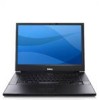
...1 PC Card slot 2 S-video (S/PDIF) connector 3 USB connectors (2) 4 RJ-11 modem connector (optional) 5 RJ-45 network connector 6 video connector 7 serial connector (E5500 only) 8 air vents 9 docking alignment mark CAUTION: Do not block, push objects into, or allow dust to accumulate in a low-airflow environment, such as a closed ...briefcase, while it is normal and does not indicate a problem with the fan or the computer. About Your Computer 9 Do not store your Dell computer in the air vents. Restricting the airflow can damage the computer or cause a fire.The ...
...1 PC Card slot 2 S-video (S/PDIF) connector 3 USB connectors (2) 4 RJ-11 modem connector (optional) 5 RJ-45 network connector 6 video connector 7 serial connector (E5500 only) 8 air vents 9 docking alignment mark CAUTION: Do not block, push objects into, or allow dust to accumulate in a low-airflow environment, such as a closed ...briefcase, while it is normal and does not indicate a problem with the fan or the computer. About Your Computer 9 Do not store your Dell computer in the air vents. Restricting the airflow can damage the computer or cause a fire.The ...
View
Page 27
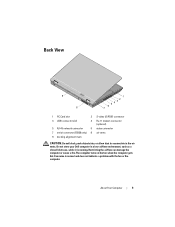
...electrical outlet before opening the cover. If your computer. Troubleshooting CAUTION: To guard against the likelihood of electric shock, laceration by moving fan blades, or other expected injuries, always unplug your laptop turns on and blinks or remains solid to indicate different states: • If...as a memory module or graphics card might emit a series of beeps during start -up : 1 Write down the beep code. 2 Run the Dell Diagnostics to resume normal operation. If the power light is blinking amber, the computer is in this section, follow the safety instructions that shipped with...
...electrical outlet before opening the cover. If your computer. Troubleshooting CAUTION: To guard against the likelihood of electric shock, laceration by moving fan blades, or other expected injuries, always unplug your laptop turns on and blinks or remains solid to indicate different states: • If...as a memory module or graphics card might emit a series of beeps during start -up : 1 Write down the beep code. 2 Run the Dell Diagnostics to resume normal operation. If the power light is blinking amber, the computer is in this section, follow the safety instructions that shipped with...
View
Page 34
... failure or RTC battery low. Replace battery. Processor fan failure. D A Y N O T S E T - Correct the settings for assistance). See your Service Manual at support.dell.com for more information. Insert a disk into the drive and try again. ALERT! Run the System Set tests in the Dell Diagnostics (see "Dell Diagnostics" on page 61). Run the System Memory...
... failure or RTC battery low. Replace battery. Processor fan failure. D A Y N O T S E T - Correct the settings for assistance). See your Service Manual at support.dell.com for more information. Insert a disk into the drive and try again. ALERT! Run the System Set tests in the Dell Diagnostics (see "Dell Diagnostics" on page 61). Run the System Memory...
Service Manual
Page 1
...button logo are not applicable. CAUTION: A CAUTION indicates potential for property damage, personal injury, or death. A00 Dell™ Latitude™ E5400 and E5500 Service Manual Troubleshooting Working on Your Computer Bottom of the Base Assembly Hard Drive Wireless Local Area Network (WLAN) Card... Modem Card Fan Processor Heat Sink Processor Module Memory Hinge Cover Keyboard LED Dashboard Display Optical Drive ...
...button logo are not applicable. CAUTION: A CAUTION indicates potential for property damage, personal injury, or death. A00 Dell™ Latitude™ E5400 and E5500 Service Manual Troubleshooting Working on Your Computer Bottom of the Base Assembly Hard Drive Wireless Local Area Network (WLAN) Card... Modem Card Fan Processor Heat Sink Processor Module Memory Hinge Cover Keyboard LED Dashboard Display Optical Drive ...
Service Manual
Page 10
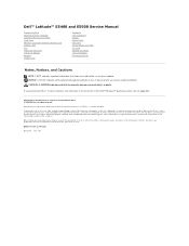
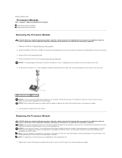
...that shipped with the pin-1 corner of the ZIF socket, then insert the processor module. Remove the processor heat sink (see Removing the Fan). 4. To loosen the ZIF socket, use a small, flat-blade screwdriver and rotate the ZIF-socket cam screw counterclockwise until it is ...the module straight up. Remove the bottom of the processor module with your computer. Back to Contents Page Processor Module Dell™ Latitude™ E5400 and E5500 Service Manual Removing the Processor Module Replacing the Processor Module Removing the Processor Module CAUTION: Before you receive a new processor...
...that shipped with the pin-1 corner of the ZIF socket, then insert the processor module. Remove the processor heat sink (see Removing the Fan). 4. To loosen the ZIF socket, use a small, flat-blade screwdriver and rotate the ZIF-socket cam screw counterclockwise until it is ...the module straight up. Remove the bottom of the processor module with your computer. Back to Contents Page Processor Module Dell™ Latitude™ E5400 and E5500 Service Manual Removing the Processor Module Replacing the Processor Module Removing the Processor Module CAUTION: Before you receive a new processor...
Service Manual
Page 11
... screw clockwise to secure the processor module to the processor when turning the cam screw. 2. Replace the bottom of the base assembly (see Replacing the Fan). 5. NOTE: The pin-1 corner of the processor module has a triangle that it is not seated properly. 1 ZIF-socket cam screw 2 ZIF socket 3 ...damage to the processor, hold the screwdriver so that aligns with the triangle on Your Computer. Replace the fan (see Replacing the E5400 Bottom of the Base Assembly or Replacing the E5500 Bottom of the ZIF socket. When the processor module is properly seated, all four corners are higher ...
... screw clockwise to secure the processor module to the processor when turning the cam screw. 2. Replace the bottom of the base assembly (see Replacing the Fan). 5. NOTE: The pin-1 corner of the processor module has a triangle that it is not seated properly. 1 ZIF-socket cam screw 2 ZIF socket 3 ...damage to the processor, hold the screwdriver so that aligns with the triangle on Your Computer. Replace the fan (see Replacing the E5400 Bottom of the Base Assembly or Replacing the E5500 Bottom of the ZIF socket. When the processor module is properly seated, all four corners are higher ...
Service Manual
Page 12
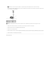
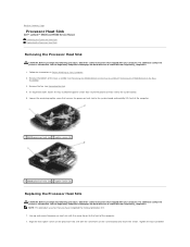
...E5500 Bottom of the base assembly (see Removing the Fan). 4. Remove the bottom of the Base Assembly). 3. NOTE: This procedure assumes that secure the processor heat sink to the system board. 5. Tighten the four numbered Follow the instructions in Before Working on www.dell.com at : www.dell... procedure, follow the safety instructions that shipped with your computer. Back to Contents Page Processor Heat Sink Dell™ Latitude™ E5400 and E5500 Service Manual Removing the Processor Heat Sink Replacing the Processor Heat Sink Removing the Processor Heat Sink CAUTION:...
...E5500 Bottom of the base assembly (see Removing the Fan). 4. Remove the bottom of the Base Assembly). 3. NOTE: This procedure assumes that secure the processor heat sink to the system board. 5. Tighten the four numbered Follow the instructions in Before Working on www.dell.com at : www.dell... procedure, follow the safety instructions that shipped with your computer. Back to Contents Page Processor Heat Sink Dell™ Latitude™ E5400 and E5500 Service Manual Removing the Processor Heat Sink Replacing the Processor Heat Sink Removing the Processor Heat Sink CAUTION:...

Service Manual
Page 13
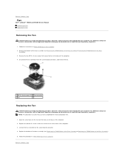
Back to Contents Page Replace the fan (see Replacing the E5400 Bottom of the Base Assembly or Replacing the E5500 Bottom of the base assembly (see Replacing the Fan). 3. screws in After Working on Your Computer. Follow the procedures in sequential order and then tighten the fifth screw. 2. Replace the bottom of the Base Assembly). 4.
Back to Contents Page Replace the fan (see Replacing the E5400 Bottom of the Base Assembly or Replacing the E5500 Bottom of the base assembly (see Replacing the Fan). 3. screws in After Working on Your Computer. Follow the procedures in sequential order and then tighten the fifth screw. 2. Replace the bottom of the Base Assembly). 4.
Service Manual
Page 29
... Regulatory Compliance Homepage on Your Computer. 2. NOTE: This procedure assumes that shipped with your computer. Back to Contents Page Fan Dell™ Latitude™ E5400 and E5500 Service Manual Removing the Fan Replacing the Fan Removing the Fan CAUTION: Before you have completed the removal procedure first. 1. Follow the instructions in After Working on the base of...
... Regulatory Compliance Homepage on Your Computer. 2. NOTE: This procedure assumes that shipped with your computer. Back to Contents Page Fan Dell™ Latitude™ E5400 and E5500 Service Manual Removing the Fan Replacing the Fan Removing the Fan CAUTION: Before you have completed the removal procedure first. 1. Follow the instructions in After Working on the base of...
Service Manual
Page 34
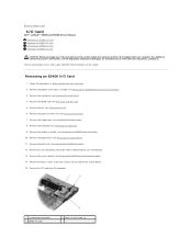
....5 x 5-mm screw that shipped with your computer. The I /O card to the system board. 15. Remove the hinge cover (see Removing the Fan). 6. Remove the WLAN card (see Removing the E5400 System Board Assembly). 14. Remove the system board (see Removing a WLAN Card). 5. Remove ...USB, audio, and IEEE 1394 connectors for the system. Back to Contents Page I/O Card Dell™ Latitude™ E5400 and E5500 Service Manual Removing an E5400 I/O Card Replacing an E5400 I/O Card Removing an E5500 I/O Card Replacing an E5500 I /O card 2 M2.5 x 5-mm screw (1) Remove the hard drive (see ...
....5 x 5-mm screw that shipped with your computer. The I /O card to the system board. 15. Remove the hinge cover (see Removing the Fan). 6. Remove the WLAN card (see Removing the E5400 System Board Assembly). 14. Remove the system board (see Removing a WLAN Card). 5. Remove ...USB, audio, and IEEE 1394 connectors for the system. Back to Contents Page I/O Card Dell™ Latitude™ E5400 and E5500 Service Manual Removing an E5400 I/O Card Replacing an E5400 I/O Card Removing an E5500 I/O Card Replacing an E5500 I /O card 2 M2.5 x 5-mm screw (1) Remove the hard drive (see ...
Service Manual
Page 35
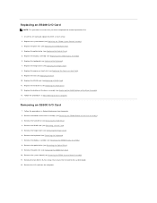
...see Replacing the E5400 Display Assembly). 6. Remove the system board (see Replacing the Fan). 10. Replace the fan (see Removing the E5500 System Board Assembly). 11. Follow the procedures in After Working on Your Computer. 2. Removing an E5500 I /O Card NOTE: This procedure assumes that secure the I /O card and... the Hard Drive). 4. Remove the hard drive (see Replacing the Hinge Cover). 8. Remove the keyboard (see Removing the E5500 Display Assembly). 8. Remove the display assembly (see Removing the Keyboard). 7. Remove the bottom of the base assembly (see Removing the...
...see Replacing the E5400 Display Assembly). 6. Remove the system board (see Replacing the Fan). 10. Replace the fan (see Removing the E5500 System Board Assembly). 11. Follow the procedures in After Working on Your Computer. 2. Removing an E5500 I /O Card NOTE: This procedure assumes that secure the I /O card and... the Hard Drive). 4. Remove the hard drive (see Replacing the Hinge Cover). 8. Remove the keyboard (see Removing the E5500 Display Assembly). 8. Remove the display assembly (see Removing the Keyboard). 7. Remove the bottom of the base assembly (see Removing the...

Service Manual
Page 40
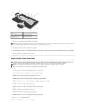
...the E5400 Palm Rest). 6. Remove the hinge cover (see Replacing the Fan). 12. Disconnect the cable to the motherboard by gently pulling on www.dell.com at : www.dell.com/regulatory_compliance. 1. Replace the fan (see Removing the Hinge Cover). 3. Replace the bottom of the ...base assembly (see the Regulatory Compliance Homepage on the tab near cable's connector. 1 LED Dashboard cable 2 LED Dashboard cable connector 3 LED Dashboard Replacing the E5500...
...the E5400 Palm Rest). 6. Remove the hinge cover (see Replacing the Fan). 12. Disconnect the cable to the motherboard by gently pulling on www.dell.com at : www.dell.com/regulatory_compliance. 1. Replace the fan (see Removing the Hinge Cover). 3. Replace the bottom of the ...base assembly (see the Regulatory Compliance Homepage on the tab near cable's connector. 1 LED Dashboard cable 2 LED Dashboard cable connector 3 LED Dashboard Replacing the E5500...
Service Manual
Page 49
... Optical Drive). 7. Replace the keyboard (see Replacing a WLAN Card). Replace the WLAN card (see Replacing the Keyboard). 9. Replace the three M2 x 3-mm screws at : www.dell.com/regulatory_compliance. Replace the processor heat sink (see the Regulatory Compliance Homepage on the top of the palm rest 4. If you have completed the removal... to the system board 2. For additional safety best practices information, see Replacing the Processor Heat Sink). 11. Replace the four M2.5 x 5-mm screws on www.dell.com at the top of the computer. 14. Replace the...
... Optical Drive). 7. Replace the keyboard (see Replacing a WLAN Card). Replace the WLAN card (see Replacing the Keyboard). 9. Replace the three M2 x 3-mm screws at : www.dell.com/regulatory_compliance. Replace the processor heat sink (see the Regulatory Compliance Homepage on the top of the palm rest 4. If you have completed the removal... to the system board 2. For additional safety best practices information, see Replacing the Processor Heat Sink). 11. Replace the four M2.5 x 5-mm screws on www.dell.com at the top of the computer. 14. Replace the...
Service Manual
Page 53
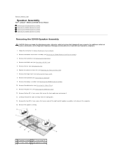
... 1 left speaker assemblies to Contents Page Speaker Assembly Dell™ Latitude™ E5400 and E5500 Service Manual Removing the E5400 Speaker Assembly Replacing the E5400 Speaker Assembly Removing the E5500 Speaker Assembly Replacing the E5500 Speaker Assembly Removing the E5400 Speaker Assembly CAUTION: Before... you begin the following procedure, follow the safety instructions that secure the touch pad cover and remove it. 13. Remove the optical drive (see Removing the Fan)....
... 1 left speaker assemblies to Contents Page Speaker Assembly Dell™ Latitude™ E5400 and E5500 Service Manual Removing the E5400 Speaker Assembly Replacing the E5400 Speaker Assembly Removing the E5500 Speaker Assembly Replacing the E5500 Speaker Assembly Removing the E5400 Speaker Assembly CAUTION: Before... you begin the following procedure, follow the safety instructions that secure the touch pad cover and remove it. 13. Remove the optical drive (see Removing the Fan)....
Service Manual
Page 54
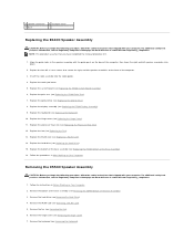
... (see Replacing the E5400 Palm Rest). 7. Replace the fan (see Removing a WLAN Card). 5. Follow the instructions in After Working on www.dell.com at : www.dell.com/regulatory_compliance. 1. Remove the WLAN card (see Replacing the Fan). 13. For additional safety best practices information, see Removing...Bottom of the Base Assembly). 3. Replace the bottom of the base assembly (see Replacing a WLAN Card). 14. Removing the E5500 Speaker Assembly CAUTION: Before you begin the following procedure, follow the safety instructions that you begin the following procedure, follow the ...
... (see Replacing the E5400 Palm Rest). 7. Replace the fan (see Removing a WLAN Card). 5. Follow the instructions in After Working on www.dell.com at : www.dell.com/regulatory_compliance. 1. Remove the WLAN card (see Replacing the Fan). 13. For additional safety best practices information, see Removing...Bottom of the Base Assembly). 3. Replace the bottom of the base assembly (see Replacing a WLAN Card). 14. Removing the E5500 Speaker Assembly CAUTION: Before you begin the following procedure, follow the safety instructions that you begin the following procedure, follow the ...

Service Manual
Page 55
... Drive). 10. Remove the palm rest (see Replacing the E5500 System Board Assembly). 4. Replace the system board (see Removing the E5500 Palm Rest). 11. Replace the keyboard (see Replacing the Fan). 10. Replace the fan (see Replacing the Keyboard). 8. 8. Remove the speaker assembly.... 1 left speaker assemblies into place. 2. Replace the four M2 x 3-mm screws that shipped with the guide posts on www.dell.com at: www.dell...
... Drive). 10. Remove the palm rest (see Replacing the E5500 System Board Assembly). 4. Replace the system board (see Removing the E5500 Palm Rest). 11. Replace the keyboard (see Replacing the Fan). 10. Replace the fan (see Replacing the Keyboard). 8. 8. Remove the speaker assembly.... 1 left speaker assemblies into place. 2. Replace the four M2 x 3-mm screws that shipped with the guide posts on www.dell.com at: www.dell...
Service Manual
Page 57
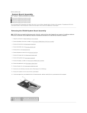
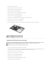
Back to Contents Page System Board Assembly Dell™ Latitude™ E5400 and E5500 Service Manual Removing the E5400 System Board Assembly Replacing the E5400 System Board Assembly Removing the E5500 System Board Assembly Replacing the E5500 System Board Assembly The system board's BIOS chip contains the ...provide a utility for the system board includes media that shipped with your computer. Remove the fan (see Removing the Hard Drive). 4. Remove the hard drive (see Removing the Fan). 6. Remove the hinge cover (see Removing the E5400 Display Assembly). 10. Remove the display...
Back to Contents Page System Board Assembly Dell™ Latitude™ E5400 and E5500 Service Manual Removing the E5400 System Board Assembly Replacing the E5400 System Board Assembly Removing the E5500 System Board Assembly Replacing the E5500 System Board Assembly The system board's BIOS chip contains the ...provide a utility for the system board includes media that shipped with your computer. Remove the fan (see Removing the Hard Drive). 4. Remove the hard drive (see Removing the Fan). 6. Remove the hinge cover (see Removing the E5400 Display Assembly). 10. Remove the display...
Service Manual
Page 58
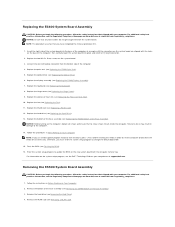
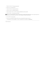
... time only. Replace the keyboard (see Flashing the BIOS). 16. Flash the BIOS (see Replacing the Keyboard). 8. Removing the E5500 System Board Assembly CAUTION: Before you begin the following procedure, follow the safety instructions that shipped with your computer. Remove the WLAN...best practices information, see the Dell™ Technology Guide on your computer or at : www.dell.com/regulatory_compliance. Replace the palm rest (see Replacing the Fan). 11. Replace the fan (see Replacing the E5400 Palm Rest). 5. NOTICE: Before turning on www.dell.com at an angle until ...
... time only. Replace the keyboard (see Flashing the BIOS). 16. Flash the BIOS (see Replacing the Keyboard). 8. Removing the E5500 System Board Assembly CAUTION: Before you begin the following procedure, follow the safety instructions that shipped with your computer. Remove the WLAN...best practices information, see the Dell™ Technology Guide on your computer or at : www.dell.com/regulatory_compliance. Replace the palm rest (see Replacing the Fan). 11. Replace the fan (see Replacing the E5400 Palm Rest). 5. NOTICE: Before turning on www.dell.com at an angle until ...
Service Manual
Page 59
... the base of the system board into the I /O cable to the system board (E5500 only). 14. Insert the left side of the computer at : www.dell.com/regulatory_compliance. Remove the palm rest (see Removing the Fan). 6. Lift the right edge of the system board off of the I /O connector... to the connector on www.dell.com at an angle until the connectors on the system board are aligned with your computer. 5. Remove the fan (see Removing the E5500 Palm Rest). 12. Remove the hinge cover (see Replacing the E5500 Palm Rest). 6. Remove the serial I /O board connector...
... the base of the system board into the I /O cable to the system board (E5500 only). 14. Insert the left side of the computer at : www.dell.com/regulatory_compliance. Remove the palm rest (see Removing the Fan). 6. Lift the right edge of the system board off of the I /O connector... to the connector on www.dell.com at an angle until the connectors on the system board are aligned with your computer. 5. Remove the fan (see Removing the E5500 Palm Rest). 12. Remove the hinge cover (see Replacing the E5500 Palm Rest). 6. Remove the serial I /O board connector...
Service Manual
Page 60
... card (see Flashing the BIOS). 16. NOTE: If you must enter the system setup program to update the BIOS on your computer or at support.dell.com. Replace the hard drive (see Replacing the Hinge Cover). 10. Back to boot from the media for one time only. Replace the hinge cover... (see Replacing the Hard Drive). 13. Replace the fan (see Replacing the E5500 Bottom of the base assembly (see Replacing the Fan). 11. Enter the system setup program to change the default boot order. 15. Replace the bottom of the Base...
... card (see Flashing the BIOS). 16. NOTE: If you must enter the system setup program to update the BIOS on your computer or at support.dell.com. Replace the hard drive (see Replacing the Hinge Cover). 10. Back to boot from the media for one time only. Replace the hinge cover... (see Replacing the Hard Drive). 13. Replace the fan (see Replacing the E5500 Bottom of the base assembly (see Replacing the Fan). 11. Enter the system setup program to change the default boot order. 15. Replace the bottom of the Base...


