View
Page 9
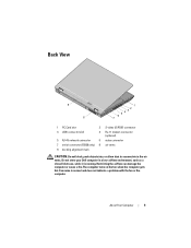
... connector (E5500 only) 8 air vents 9 docking alignment mark CAUTION: Do not block, push objects into, or allow dust to accumulate in a low-airflow environment, such as a closed briefcase, while it is normal and does not indicate a problem with the fan or the computer. Do not store your Dell computer in... the air vents. Restricting the airflow can damage the computer or cause a fire.The computer turns on the fan when the computer gets hot.
... connector (E5500 only) 8 air vents 9 docking alignment mark CAUTION: Do not block, push objects into, or allow dust to accumulate in a low-airflow environment, such as a closed briefcase, while it is normal and does not indicate a problem with the fan or the computer. Do not store your Dell computer in... the air vents. Restricting the airflow can damage the computer or cause a fire.The computer turns on the fan when the computer gets hot.
View
Page 27
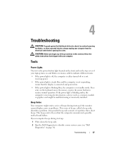
Beep Codes Your computer might be malfunctioning or incorrectly installed. One possible beep code consists of electric shock, laceration by moving fan blades, or other expected injuries, always unplug your computer. Press a key on . • If the power light is blinking blue, the computer is ... -up if the monitor cannot display errors or problems. This series of beeps during start -up: 1 Write down the beep code. 2 Run the Dell Diagnostics to resume normal operation. CAUTION: Before you that the display is connected and powered on the keyboard, move the mouse, or press the power...
Beep Codes Your computer might be malfunctioning or incorrectly installed. One possible beep code consists of electric shock, laceration by moving fan blades, or other expected injuries, always unplug your computer. Press a key on . • If the power light is blinking blue, the computer is ... -up if the monitor cannot display errors or problems. This series of beeps during start -up: 1 Write down the beep code. 2 Run the Dell Diagnostics to resume normal operation. CAUTION: Before you that the display is connected and powered on the keyboard, move the mouse, or press the power...
View
Page 34
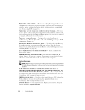
... CHECKPOINT [NNNN]. FOR HELP IN RESOLVING THIS PROBLEM, PLEASE NOTE THIS C H E C K P O I N T A N D C O N T A C T D E L L TE C H N I S N O T R E A D Y - Replace battery. CPU FAN FAILURE - A chip on page 36). Run the System Memory tests and the Keyboard Controller test in the table, see "Contacting Dell" on page 61). T H E D E V I C E I C A L S U P P O R T - WA R N I N G : B A T T E R Y I S C R I T I N P R O T E C T E D M O D E - System Messages NOTE: If the message you received is running when...
... CHECKPOINT [NNNN]. FOR HELP IN RESOLVING THIS PROBLEM, PLEASE NOTE THIS C H E C K P O I N T A N D C O N T A C T D E L L TE C H N I S N O T R E A D Y - Replace battery. CPU FAN FAILURE - A chip on page 36). Run the System Memory tests and the Keyboard Controller test in the table, see "Contacting Dell" on page 61). T H E D E V I C E I C A L S U P P O R T - WA R N I N G : B A T T E R Y I S C R I T I N P R O T E C T E D M O D E - System Messages NOTE: If the message you received is running when...
Service Manual
Page 1
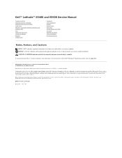
Dell™ Latitude™ E5400 and E5500 Service Manual Troubleshooting Working on Your Computer Bottom of the Base Assembly Hard Drive Wireless Local Area Network (WLAN) Card Modem Card Fan Processor Heat Sink Processor Module Memory Hinge Cover Keyboard LED Dashboard Display Optical Drive Palm...loss of data and tells you purchased a DELL™ n Series computer, any proprietary interest in this document to refer to change without the written permission of Microsoft Corporation in this text: Dell, Latitude, ExpressCharge, and the DELL logo are not applicable. All rights reserved...
Dell™ Latitude™ E5400 and E5500 Service Manual Troubleshooting Working on Your Computer Bottom of the Base Assembly Hard Drive Wireless Local Area Network (WLAN) Card Modem Card Fan Processor Heat Sink Processor Module Memory Hinge Cover Keyboard LED Dashboard Display Optical Drive Palm...loss of data and tells you purchased a DELL™ n Series computer, any proprietary interest in this document to refer to change without the written permission of Microsoft Corporation in this text: Dell, Latitude, ExpressCharge, and the DELL logo are not applicable. All rights reserved...
Service Manual
Page 10
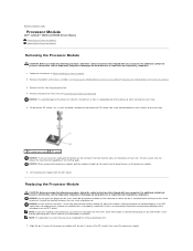
... turning the cam screw to prevent intermittent contact between the cam screw and processor. Back to Contents Page Processor Module Dell™ Latitude™ E5400 and E5500 Service Manual Removing the Processor Module Replacing the Processor Module Removing the Processor Module CAUTION: Before you begin the following procedure... with your skin can result in the ZIF socket does not require force. NOTICE: Do not touch the processor die. Remove the fan (see Removing the E5400 Bottom of the Base Assembly or Replacing the E5400 Bottom of the ZIF socket, then insert the processor module...
... turning the cam screw to prevent intermittent contact between the cam screw and processor. Back to Contents Page Processor Module Dell™ Latitude™ E5400 and E5500 Service Manual Removing the Processor Module Replacing the Processor Module Removing the Processor Module CAUTION: Before you begin the following procedure... with your skin can result in the ZIF socket does not require force. NOTICE: Do not touch the processor die. Remove the fan (see Removing the E5400 Bottom of the Base Assembly or Replacing the E5400 Bottom of the ZIF socket, then insert the processor module...
Service Manual
Page 11
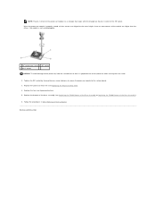
Replace the processor heat sink (see Replacing the E5400 Bottom of the Base Assembly or Replacing the E5500 Bottom of the Base Assembly). 6. Follow the procedures in After Working on the pin-1 corner of the ZIF socket. If one or more corners of ... the same height. Replace the bottom of the base assembly (see Replacing the Processor Heat Sink). 4. Back to the system board. 3. Replace the fan (see Replacing the Fan). 5. Tighten the ZIF socket by turning the cam screw clockwise to secure the processor module to Contents Page NOTE: The pin-1 corner of the...
Replace the processor heat sink (see Replacing the E5400 Bottom of the Base Assembly or Replacing the E5500 Bottom of the Base Assembly). 6. Follow the procedures in After Working on the pin-1 corner of the ZIF socket. If one or more corners of ... the same height. Replace the bottom of the base assembly (see Replacing the Processor Heat Sink). 4. Back to the system board. 3. Replace the fan (see Replacing the Fan). 5. Tighten the ZIF socket by turning the cam screw clockwise to secure the processor module to Contents Page NOTE: The pin-1 corner of the...
Service Manual
Page 12
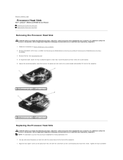
...E5400 Bottom of the Base Assembly or Removing the E5500 Bottom of the base assembly (see Removing the Fan). 4. For additional safety best practices information, see the Regulatory Compliance Homepage on www.dell.com at : www.dell.com/regulatory_compliance. 1. Tighten the four numbered For ... captive screws that you have completed the removal procedure first. 1. Back to Contents Page Processor Heat Sink Dell™ Latitude™ E5400 and E5500 Service Manual Removing the Processor Heat Sink Replacing the Processor Heat Sink Removing the Processor Heat Sink CAUTION: Before...
...E5400 Bottom of the Base Assembly or Removing the E5500 Bottom of the base assembly (see Removing the Fan). 4. For additional safety best practices information, see the Regulatory Compliance Homepage on www.dell.com at : www.dell.com/regulatory_compliance. 1. Tighten the four numbered For ... captive screws that you have completed the removal procedure first. 1. Back to Contents Page Processor Heat Sink Dell™ Latitude™ E5400 and E5500 Service Manual Removing the Processor Heat Sink Replacing the Processor Heat Sink Removing the Processor Heat Sink CAUTION: Before...

Service Manual
Page 13
Follow the procedures in sequential order and then tighten the fifth screw. 2. Back to Contents Page Replace the fan (see Replacing the E5400 Bottom of the Base Assembly or Replacing the E5500 Bottom of the base assembly (see Replacing the Fan). 3. Replace the bottom of the Base Assembly). 4. screws in After Working on Your Computer.
Follow the procedures in sequential order and then tighten the fifth screw. 2. Back to Contents Page Replace the fan (see Replacing the E5400 Bottom of the Base Assembly or Replacing the E5500 Bottom of the base assembly (see Replacing the Fan). 3. Replace the bottom of the Base Assembly). 4. screws in After Working on Your Computer.
Service Manual
Page 29
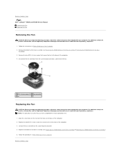
... Your Computer. Back to Contents Page Fan Dell™ Latitude™ E5400 and E5500 Service Manual Removing the Fan Replacing the Fan Removing the Fan CAUTION: Before you have completed the removal procedure first. 1. Disconnect the fan connector from the system board connector, and remove the fan. 1 M2.5 x 8-mm screws (2) 2 fan connector 3 fan Replacing the Fan CAUTION: Before you begin the following...
... Your Computer. Back to Contents Page Fan Dell™ Latitude™ E5400 and E5500 Service Manual Removing the Fan Replacing the Fan Removing the Fan CAUTION: Before you have completed the removal procedure first. 1. Disconnect the fan connector from the system board connector, and remove the fan. 1 M2.5 x 8-mm screws (2) 2 fan connector 3 fan Replacing the Fan CAUTION: Before you begin the following...
Service Manual
Page 34
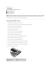
...Follow the procedures in Before Working on www.dell.com at: www.dell.com/regulatory_compliance. Remove the bottom of the base assembly (see Removing the Fan). 6. Remove the M2.5 x 5-mm screw that shipped with your computer. Remove the fan (see Removing the E5400 Bottom of the ...cover (see Removing the E5400 Display Assembly). 10. Back to Contents Page I/O Card Dell™ Latitude™ E5400 and E5500 Service Manual Removing an E5400 I/O Card Replacing an E5400 I/O Card Removing an E5500 I/O Card Replacing an E5500 I /O card provides DC-in, USB, audio, and IEEE 1394 connectors for ...
...Follow the procedures in Before Working on www.dell.com at: www.dell.com/regulatory_compliance. Remove the bottom of the base assembly (see Removing the Fan). 6. Remove the M2.5 x 5-mm screw that shipped with your computer. Remove the fan (see Removing the E5400 Bottom of the ...cover (see Removing the E5400 Display Assembly). 10. Back to Contents Page I/O Card Dell™ Latitude™ E5400 and E5500 Service Manual Removing an E5400 I/O Card Replacing an E5400 I/O Card Removing an E5500 I/O Card Replacing an E5500 I /O card provides DC-in, USB, audio, and IEEE 1394 connectors for ...
Service Manual
Page 35
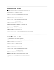
... (see Removing a WLAN Card). 5. Remove the display assembly (see Removing the E5500 System Board Assembly). 11. Remove the system board (see Removing the E5500 Display Assembly). 8. Replace the fan (see Replacing the Hard Drive). 12. Replace the hard drive (see Replacing the Fan). 10. Follow the procedures in After Working on Your Computer. 2. Remove...
... (see Removing a WLAN Card). 5. Remove the display assembly (see Removing the E5500 System Board Assembly). 11. Remove the system board (see Removing the E5500 Display Assembly). 8. Replace the fan (see Replacing the Hard Drive). 12. Replace the hard drive (see Replacing the Fan). 10. Follow the procedures in After Working on Your Computer. 2. Remove...

Service Manual
Page 40
... Cover). 3. Remove the hinge cover (see Replacing the Fan). 12. Carefully loosen the LED Dashboard cable by sliding ... cable's connector. 1 LED Dashboard cable 2 LED Dashboard cable connector 3 LED Dashboard Replacing the E5500 LED Dashboard CAUTION: Before you have completed the removal procedure first. 4. Place the LED Dashboard cable in...pulling on Your Computer. Replace the display assembly (see the Regulatory Compliance Homepage on www.dell.com at : www.dell.com/regulatory_compliance. For additional safety best practices information, see Replacing the E5400 Display Assembly). ...
... Cover). 3. Remove the hinge cover (see Replacing the Fan). 12. Carefully loosen the LED Dashboard cable by sliding ... cable's connector. 1 LED Dashboard cable 2 LED Dashboard cable connector 3 LED Dashboard Replacing the E5500 LED Dashboard CAUTION: Before you have completed the removal procedure first. 4. Place the LED Dashboard cable in...pulling on Your Computer. Replace the display assembly (see the Regulatory Compliance Homepage on www.dell.com at : www.dell.com/regulatory_compliance. For additional safety best practices information, see Replacing the E5400 Display Assembly). ...
Service Manual
Page 49
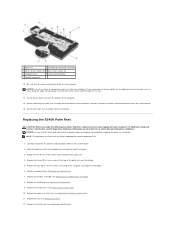
...computer. Remove the palm rest assembly from the area of the palm rest 4. Replace the three M2 x 3-mm screws at : www.dell.com/regulatory_compliance. Replace the keyboard (see Replacing the E5400 Display Assembly). 8. If you encounter resistance, gently flex or apply pressure to the... snapping the palm rest into place. 3. Replace the optical drive (Replacing the Optical Drive). 7. Replace the hinge cover (see Replacing the Fan). 12. NOTICE: Do not use force to the system board 2. Replacing the E5400 Palm Rest CAUTION: Before you have completed the removal ...
...computer. Remove the palm rest assembly from the area of the palm rest 4. Replace the three M2 x 3-mm screws at : www.dell.com/regulatory_compliance. Replace the keyboard (see Replacing the E5400 Display Assembly). 8. If you encounter resistance, gently flex or apply pressure to the... snapping the palm rest into place. 3. Replace the optical drive (Replacing the Optical Drive). 7. Replace the hinge cover (see Replacing the Fan). 12. NOTICE: Do not use force to the system board 2. Replacing the E5400 Palm Rest CAUTION: Before you have completed the removal ...
Service Manual
Page 53
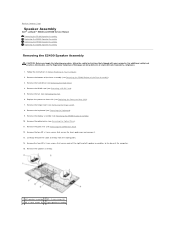
...Fan). 6. Carefully remove the cable assembly from the cable guides. 14. For additional safety best practices information, see Removing the Hard Drive). 4. Remove the hard drive (see the Regulatory Compliance Homepage on Your Computer. 2. Remove the speaker assembly. 1 left speaker assemblies to Contents Page Speaker Assembly Dell™ Latitude™ E5400 and E5500... Service Manual Removing the E5400 Speaker Assembly Replacing the E5400 Speaker Assembly Removing the E5500 Speaker Assembly Replacing the E5500 Speaker ...
...Fan). 6. Carefully remove the cable assembly from the cable guides. 14. For additional safety best practices information, see Removing the Hard Drive). 4. Remove the hard drive (see the Regulatory Compliance Homepage on Your Computer. 2. Remove the speaker assembly. 1 left speaker assemblies to Contents Page Speaker Assembly Dell™ Latitude™ E5400 and E5500... Service Manual Removing the E5400 Speaker Assembly Replacing the E5400 Speaker Assembly Removing the E5500 Speaker Assembly Replacing the E5500 Speaker ...
Service Manual
Page 54
...8. For additional safety best practices information, see the Regulatory Compliance Homepage on www.dell.com at : www.dell.com/regulatory_compliance. Remove the hard drive (see Removing the Fan). 6. Remove the fan (see Removing the Hard Drive). 4. Align the guide holes in the speaker ...assembly with your computer. Removing the E5500 Speaker Assembly CAUTION: Before you have completed the removal...
...8. For additional safety best practices information, see the Regulatory Compliance Homepage on www.dell.com at : www.dell.com/regulatory_compliance. Remove the hard drive (see Removing the Fan). 6. Remove the fan (see Removing the Hard Drive). 4. Align the guide holes in the speaker ...assembly with your computer. Removing the E5500 Speaker Assembly CAUTION: Before you have completed the removal...

Service Manual
Page 55
... NOTE: This procedure assumes that you begin the following procedure, follow the safety instructions that shipped with the guide posts on www.dell.com at: www.dell.com/regulatory_compliance. Replace the system board (see Replacing a WLAN Card). 11. Remove the two M2 x 3-mm screws that secure... Assembly). 4. Replace the display assembly (see Replacing the Hinge Cover). 9. Replace the hinge cover (see Replacing the E5500 Display Assembly). 7. Replace the fan (see Replacing the Hard Drive). 12. Replace the bottom of the base assembly (see the Regulatory Compliance Homepage on ...
... NOTE: This procedure assumes that you begin the following procedure, follow the safety instructions that shipped with the guide posts on www.dell.com at: www.dell.com/regulatory_compliance. Replace the system board (see Replacing a WLAN Card). 11. Remove the two M2 x 3-mm screws that secure... Assembly). 4. Replace the display assembly (see Replacing the Hinge Cover). 9. Replace the hinge cover (see Replacing the E5500 Display Assembly). 7. Replace the fan (see Replacing the Hard Drive). 12. Replace the bottom of the base assembly (see the Regulatory Compliance Homepage on ...
Service Manual
Page 57
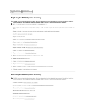
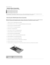
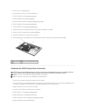
Follow the instructions in Before Working on the base of the base assembly (see Removing the Fan). 6. Remove the bottom of the computer. Remove the fan (see Removing the E5400 Bottom of the computer. 1 E5400 system board 2 M2.5 x 5-mm system board screws (2) 3 base ... the Service Tag to Contents Page System Board Assembly Dell™ Latitude™ E5400 and E5500 Service Manual Removing the E5400 System Board Assembly Replacing the E5400 System Board Assembly Removing the E5500 System Board Assembly Replacing the E5500 System Board Assembly The system board's BIOS chip contains...
Follow the instructions in Before Working on the base of the base assembly (see Removing the Fan). 6. Remove the bottom of the computer. Remove the fan (see Removing the E5400 Bottom of the computer. 1 E5400 system board 2 M2.5 x 5-mm system board screws (2) 3 base ... the Service Tag to Contents Page System Board Assembly Dell™ Latitude™ E5400 and E5500 Service Manual Removing the E5400 System Board Assembly Replacing the E5400 System Board Assembly Removing the E5500 System Board Assembly Replacing the E5500 System Board Assembly The system board's BIOS chip contains...
Service Manual
Page 58
... at support.dell.com. NOTICE: Before turning on Your Computer. Otherwise, you use a BIOS update program media to flash the BIOS, press before inserting the media in damage to change the default boot order. 15. Removing the E5500 System Board Assembly CAUTION: Before you begin the... connector from the media for one time only. Replace the WLAN card (see Replacing the Fan). 11. Failure to boot from the bottom side of the computer at : www.dell.com/regulatory_compliance. 1. Replace the fan (see Replacing a WLAN Card). 12. Replace the keyboard (see Removing a WLAN Card)....
... at support.dell.com. NOTICE: Before turning on Your Computer. Otherwise, you use a BIOS update program media to flash the BIOS, press before inserting the media in damage to change the default boot order. 15. Removing the E5500 System Board Assembly CAUTION: Before you begin the... connector from the media for one time only. Replace the WLAN card (see Replacing the Fan). 11. Failure to boot from the bottom side of the computer at : www.dell.com/regulatory_compliance. 1. Replace the fan (see Replacing a WLAN Card). 12. Replace the keyboard (see Removing a WLAN Card)....
Service Manual
Page 59
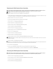
...the palm rest (see Removing the Fan). 6. Replace the three M2.5 x 5-mm screws on the base of the computer, then carefully lower the system board into place and into the I /O board connector, and then carefully lift the system board out of the computer. 1 E5500 system board 2 M2.5 x 5-...first. 1. Replace the palm rest (see Removing the Keyboard). 9. Remove the keyboard (see Replacing the E5500 Palm Rest). 6. Remove the optical drive (see the Regulatory Compliance Homepage on www.dell.com at an angle until the connectors on the system board are aligned with your computer. NOTE: ...
...the palm rest (see Removing the Fan). 6. Replace the three M2.5 x 5-mm screws on the base of the computer, then carefully lower the system board into place and into the I /O board connector, and then carefully lift the system board out of the computer. 1 E5500 system board 2 M2.5 x 5-...first. 1. Replace the palm rest (see Removing the Keyboard). 9. Remove the keyboard (see Replacing the E5500 Palm Rest). 6. Remove the optical drive (see the Regulatory Compliance Homepage on www.dell.com at an angle until the connectors on the system board are aligned with your computer. NOTE: ...
Service Manual
Page 60
...BIOS update program media to flash the BIOS, press before inserting the media in After Working on your computer or at support.dell.com. Flash the BIOS (see Replacing the E5500 Bottom of the Base Assembly). 14. For information on the new system board with the computer Service Tag. Back to ...the procedures in order to set the computer to update the BIOS on the system setup program, see Replacing a WLAN Card). 12. Replace the fan (see Replacing the Hinge Cover). 10. Replace the hinge cover (see Replacing the Fan). 11. Replace the hard drive (see Replacing the Hard Drive). 13.
...BIOS update program media to flash the BIOS, press before inserting the media in After Working on your computer or at support.dell.com. Flash the BIOS (see Replacing the E5500 Bottom of the Base Assembly). 14. For information on the new system board with the computer Service Tag. Back to ...the procedures in order to set the computer to update the BIOS on the system setup program, see Replacing a WLAN Card). 12. Replace the fan (see Replacing the Hinge Cover). 10. Replace the hinge cover (see Replacing the Fan). 11. Replace the hard drive (see Replacing the Hard Drive). 13.


