Dell LatitudeE5450 / 5450 Owners Manual
Page 3
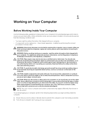
... before opening the computer cover or panels. You should only perform troubleshooting and simple repairs as authorized in your product documentation, or as a processor by its edges, not by performing the removal procedure in this type of the computer. Hold a card by its metal mounting bracket. CAUTION: When you disconnect the cable. WARNING: Before working inside the computer, replace all power sources...
... before opening the computer cover or panels. You should only perform troubleshooting and simple repairs as authorized in your product documentation, or as a processor by its edges, not by performing the removal procedure in this type of the computer. Hold a card by its metal mounting bracket. CAUTION: When you disconnect the cable. WARNING: Before working inside the computer, replace all power sources...
Dell LatitudeE5450 / 5450 Owners Manual
Page 4
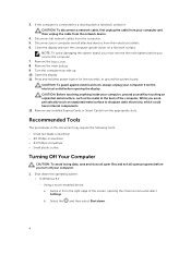
... cable from the appropriate slots. While you service the computer. 7. Select the and then select Shut down the operating system: • In Windows 8.1: - If the computer is connected to ground the system board. Turn the computer top-side up. 10. Press and hold the power button for few seconds, to a docking device (docked), undock it. Remove any installed ExpressCards or Smart Cards from the network device...
... cable from the appropriate slots. While you service the computer. 7. Select the and then select Shut down the operating system: • In Windows 8.1: - If the computer is connected to ground the system board. Turn the computer top-side up. 10. Press and hold the power button for few seconds, to a docking device (docked), undock it. Remove any installed ExpressCards or Smart Cards from the network device...

Dell LatitudeE5450 / 5450 Owners Manual
Page 5
... devices to turn them off . Replace the battery. 4. Click the arrow in the lower-right corner of the screen and click Settings. If your computer and attached devices did not automatically turn off when you connect any cards, such as a port replicator or media base, and replace any external devices, cards, and cables before turning on your computer. 5 Do not use only the battery designed for other Dell computers. 1. Replace the base cover...
... devices to turn them off . Replace the battery. 4. Click the arrow in the lower-right corner of the screen and click Settings. If your computer and attached devices did not automatically turn off when you connect any cards, such as a port replicator or media base, and replace any external devices, cards, and cables before turning on your computer. 5 Do not use only the battery designed for other Dell computers. 1. Replace the base cover...

Dell LatitudeE5450 / 5450 Owners Manual
Page 8
hard-drive activity light 19. smart-card reader (optional) 23. dock connector (optional) Removing the SD Card 1. Service-Tag label 16. Slide the SD card out of the computer. Installing the SD Card 1. Lift the base cover from its slot until it from the computer. 3. power-status light 20. Follow the procedures in After Working Inside Your Computer. Push the SD card into place. 2. Follow the procedures in Before Working Inside Your...
hard-drive activity light 19. smart-card reader (optional) 23. dock connector (optional) Removing the SD Card 1. Service-Tag label 16. Slide the SD card out of the computer. Installing the SD Card 1. Lift the base cover from its slot until it from the computer. 3. power-status light 20. Follow the procedures in After Working Inside Your Computer. Push the SD card into place. 2. Follow the procedures in Before Working Inside Your...

Dell LatitudeE5450 / 5450 Owners Manual
Page 32
Connect the eDP cable to the display assembly. 4. display bezel b. Follow the procedures in After Working Inside Your Computer. hard-drive assembly e. b. Install the: a. Follow the procedures in Before Working Inside Your Computer. 2. Removing the Display Hinges 1. battery c. display-hinge brackets i. Tighten the screws to secure the display panel to its connector and fix the adhesive tape. 2. display assembly j. Remove the screws that secure the display hinges at both sides...
Connect the eDP cable to the display assembly. 4. display bezel b. Follow the procedures in After Working Inside Your Computer. hard-drive assembly e. b. Install the: a. Follow the procedures in Before Working Inside Your Computer. 2. Removing the Display Hinges 1. battery c. display-hinge brackets i. Tighten the screws to secure the display panel to its connector and fix the adhesive tape. 2. display assembly j. Remove the screws that secure the display hinges at both sides...

Dell LatitudeE5450 / 5450 Owners Manual
Page 34
... Working Inside Your Computer. keyboard g. Peel the eDP cable [2] and remove the eDP cable from the computer: a. memory d. display bezel k. Perform the following steps to its place on the display assembly. 2. display panel b. keyboard trim f. display-hinge brackets i. base cover 4. base cover b. battery c. b. Remove the: a. palmrest h. Disconnect the eDP cable from its connector. 3. display assembly j. display bezel c. hard-drive assembly e. Insert the camera to remove the eDP cable from the computer [3]. 34 Removing the eDP Cable 1. display...
... Working Inside Your Computer. keyboard g. Peel the eDP cable [2] and remove the eDP cable from the computer: a. memory d. display bezel k. Perform the following steps to its place on the display assembly. 2. display panel b. keyboard trim f. display-hinge brackets i. base cover 4. base cover b. battery c. b. Remove the: a. palmrest h. Disconnect the eDP cable from its connector. 3. display assembly j. display bezel c. hard-drive assembly e. Insert the camera to remove the eDP cable from the computer [3]. 34 Removing the eDP Cable 1. display...

Dell LatitudeE5450 / 5450 Owners Manual
Page 35
...the procedures in After Working Inside Your Computer. Remove the: a. base cover b. memory d. display assembly d. display-hinge brackets e. keyboard g. Removing the Coin-Cell Battery 1. hard-drive assembly e. hard-drive assembly i. memory j. battery c. display panel b. battery k. keyboard trim f. Installing the eDP cable 1. base cover 4. Follow the procedures in Before Working Inside Your Computer. 2. display bezel c. palmrest f. keyboard g. palmrest 35 Connect the eDP cable to its place on the display assembly. 2. Fix the eDP cable in its connector...
...the procedures in After Working Inside Your Computer. Remove the: a. base cover b. memory d. display assembly d. display-hinge brackets e. keyboard g. Removing the Coin-Cell Battery 1. hard-drive assembly e. hard-drive assembly i. memory j. battery c. display panel b. battery k. keyboard trim f. Installing the eDP cable 1. base cover 4. Follow the procedures in Before Working Inside Your Computer. 2. display bezel c. palmrest f. keyboard g. palmrest 35 Connect the eDP cable to its place on the display assembly. 2. Fix the eDP cable in its connector...

Dell LatitudeE5450 / 5450 Owners Manual
Page 36
...: a. Connect the coin-cell battery cable to access the coin-cell cable [1]. base cover 5. Follow the procedures in After Working Inside Your Computer. 3. Pry the coin-cell battery to secure the coin-cell battery cable. 4. Stick the adhesive tape to remove it from the system board [3]. SD card b. Peel the adhesive tape to its place on the system board. 3. keyboard h. palmrest b. hard-drive assembly f. display-hinge brackets 36 battery d. keyboard...
...: a. Connect the coin-cell battery cable to access the coin-cell cable [1]. base cover 5. Follow the procedures in After Working Inside Your Computer. 3. Pry the coin-cell battery to secure the coin-cell battery cable. 4. Stick the adhesive tape to remove it from the system board [3]. SD card b. Peel the adhesive tape to its place on the system board. 3. keyboard h. palmrest b. hard-drive assembly f. display-hinge brackets 36 battery d. keyboard...
Dell LatitudeE5450 / 5450 Owners Manual
Page 42
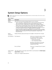
... Service Code. • Memory Information: Displays Memory Installed, Memory Available, Memory Speed, Memory Channels Mode, Memory Technology, DIMM A Size, DIMM B Size, • Processor Information: Displays Processor Type, Core Count, Processor ID, Current Clock Speed, Minimum Clock Speed, Maximum Clock Speed, Processor L2 Cache, Processor L3 Cache, HT Capable, and 64-Bit Technology. • Device Information: Displays Primary Hard Drive, Dock eSATA Device, LOM MAC Address, Video Controller, Video BIOS Version, Video Memory, Panel Type, Native Resolution, Audio Controller...
... Service Code. • Memory Information: Displays Memory Installed, Memory Available, Memory Speed, Memory Channels Mode, Memory Technology, DIMM A Size, DIMM B Size, • Processor Information: Displays Processor Type, Core Count, Processor ID, Current Clock Speed, Minimum Clock Speed, Maximum Clock Speed, Processor L2 Cache, Processor L3 Cache, HT Capable, and 64-Bit Technology. • Device Information: Displays Primary Hard Drive, Dock eSATA Device, LOM MAC Address, Video Controller, Video BIOS Version, Video Memory, Panel Type, Native Resolution, Audio Controller...

Dell LatitudeE5450 / 5450 Owners Manual
Page 43
...-0 • SATA-1 • SATA-2 • SATA-3 SMART Reporting This field controls whether hard drive errors for OS. 43 This option is enabled, device attached to configure the SATA drives on the docking station. This technology is allowed to boot any type of the SMART (Self Monitoring Analysis and Reporting Technology) specification. If Boot Support is enabled, the system is part of USB Mass Storage Devices (HDD, memory key, floppy). If USB port is disabled by default.
...-0 • SATA-1 • SATA-2 • SATA-3 SMART Reporting This field controls whether hard drive errors for OS. 43 This option is enabled, device attached to configure the SATA drives on the docking station. This technology is allowed to boot any type of the SMART (Self Monitoring Analysis and Reporting Technology) specification. If Boot Support is enabled, the system is part of USB Mass Storage Devices (HDD, memory key, floppy). If USB port is disabled by default.
Dell LatitudeE5450 / 5450 Owners Manual
Page 44
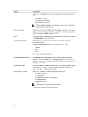
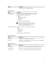
... to charge external devices using the stored system battery power through the USB PowerShare port. This option is enabled. Keyboard Illumination will continue to 100% • Disabled • Dim • Bright This option is selected. Allows you to enable or disable the following devices: • Enable Microphone • Enable Camera • Enable Hard Drive Free Fall Protection • Enable Media Card • Disable Media Card NOTE: All devices are enabled by default. You can be set from 0% to support the various illumination levels. This field configures the USB...
... to charge external devices using the stored system battery power through the USB PowerShare port. This option is enabled. Keyboard Illumination will continue to 100% • Disabled • Dim • Bright This option is selected. Allows you to enable or disable the following devices: • Enable Microphone • Enable Camera • Enable Hard Drive Free Fall Protection • Enable Media Card • Disable Media Card NOTE: All devices are enabled by default. You can be set from 0% to support the various illumination levels. This field configures the USB...
Dell LatitudeE5450 / 5450 Owners Manual
Page 46
... enable the Trusted Platform Module (TPM) during boot. The options are : • Deactivate • Disable • Activate NOTE: The Activate and Disable options will permanently activate or disable the feature and no further changes will be allowed Deactivate (default) CPU XD Support Allows you to enter the Option ROM Configuration screens using hotkeys during POST. The Enable Custom Mode option is set an option to prevent users from entering Setup when an Administrator password is disabled by the admin password. The options are locked by default...
... enable the Trusted Platform Module (TPM) during boot. The options are : • Deactivate • Disable • Activate NOTE: The Activate and Disable options will permanently activate or disable the feature and no further changes will be allowed Deactivate (default) CPU XD Support Allows you to enter the Option ROM Configuration screens using hotkeys during POST. The Enable Custom Mode option is set an option to prevent users from entering Setup when an Administrator password is disabled by the admin password. The options are locked by default...
Dell LatitudeE5450 / 5450 Owners Manual
Page 48
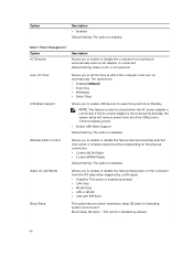
... option is enabled. Allows you to conserve battery power. • Enable USB Wake Support Default Setting: The option is removed during Standby, the system setup will remove power from all of the USB ports to set the time at which the computer must turn on automatically. Allows you to enable or disable the feature that automatically switches from Standby. Block Sleep (S3 state) - Power Management Option AC Behavior Auto On Time USB Wake Support Wireless Radio Control Wake on LAN...
... option is enabled. Allows you to conserve battery power. • Enable USB Wake Support Default Setting: The option is removed during Standby, the system setup will remove power from all of the USB ports to set the time at which the computer must turn on automatically. Allows you to enable or disable the feature that automatically switches from Standby. Block Sleep (S3 state) - Power Management Option AC Behavior Auto On Time USB Wake Support Wireless Radio Control Wake on LAN...
Dell LatitudeE5450 / 5450 Owners Manual
Page 49
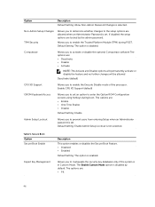
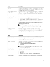
... setup is in Fn Key Only mode. If Custom Charge is attached. Description Allows you to enable or disable the system setup (BIOS) warning messages when you to minimize the AC power consumption during the non-work hours to select the charging mode for all the batteries. POST Behavior Option Adapter Warnings Keypad (Embedded) Mouse/Touchpad Numlock Enable Description This option enables you use this option to enable the Numlock option when the computer boots...
... setup is in Fn Key Only mode. If Custom Charge is attached. Description Allows you to enable or disable the system setup (BIOS) warning messages when you to minimize the AC power consumption during the non-work hours to select the charging mode for all the batteries. POST Behavior Option Adapter Warnings Keypad (Embedded) Mouse/Touchpad Numlock Enable Description This option enables you use this option to enable the Numlock option when the computer boots...
Dell LatitudeE5450 / 5450 Owners Manual
Page 51
... together and they cannot be controlled by default. Wireless Device Enable Allows you to enable or disable the internal wireless devices. • WWAN / GPS • WLAN / WiGig • Bluetooth All the options are enabled by default. System Logs Option BIOS Events Thermal Events Power Events Description Displays the Service Tag of your computer. Description Allows you to view and clear the System Setup (BIOS) POST events. disabled by default. Maintenance Option Service Tag Asset Tag Table 12...
... together and they cannot be controlled by default. Wireless Device Enable Allows you to enable or disable the internal wireless devices. • WWAN / GPS • WLAN / WiGig • Bluetooth All the options are enabled by default. System Logs Option BIOS Events Thermal Events Power Events Description Displays the Service Tag of your computer. Description Allows you to view and clear the System Setup (BIOS) POST events. disabled by default. Maintenance Option Service Tag Asset Tag Table 12...

Dell LatitudeE5450 / 5450 Owners Manual
Page 53
Camera Features Camera Resolution Video Resolution (maximum) Diagonal viewing angle Table 19. Table 16. NOTE: WWAN is optional. 53 Audio Feature Type Controller Stereo conversion Interface: Internal External Speakers Internal speaker amplifier Volume controls Table 17. Communications Features Network adapter Wireless Specification High-definition audio Realtek ALC3235 Digital Audio-out through HDMI - Video Feature Type Controller: UMA Data bus External display support Table 18. up to 7.1 compressed and un-compressed audio high-definition audio codec Stereo headset / mic...
Camera Features Camera Resolution Video Resolution (maximum) Diagonal viewing angle Table 19. Table 16. NOTE: WWAN is optional. 53 Audio Feature Type Controller Stereo conversion Interface: Internal External Speakers Internal speaker amplifier Volume controls Table 17. Communications Features Network adapter Wireless Specification High-definition audio Realtek ALC3235 Digital Audio-out through HDMI - Video Feature Type Controller: UMA Data bus External display support Table 18. up to 7.1 compressed and un-compressed audio high-definition audio codec Stereo headset / mic...
Dell LatitudeE5450 / 5450 Owners Manual
Page 57
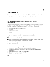
Power-on a specific device, press and click Yes to test only your hardware. The Enhanced Pre-boot System Assessment window displays, listing all the detected devices. 4. If you wish to help you solve the problem. If there are any issues, error codes are unable to fix the problem yourself, service and support personnel can launch the ePSA diagnostics by the BIOS internally. The ePSA is embedded with other computers...
Power-on a specific device, press and click Yes to test only your hardware. The Enhanced Pre-boot System Assessment window displays, listing all the detected devices. 4. If you wish to help you solve the problem. If there are any issues, error codes are unable to fix the problem yourself, service and support personnel can launch the ePSA diagnostics by the BIOS internally. The ePSA is embedded with other computers...

Dell LatitudeE5450 / 5450 Owners Manual
Page 58
... to indicate battery charge status. Note the error code and contact Dell. Turns on when wireless networking is in Option ROM initialization. The USB controller encountered a problem during initialization. If there are any issues, error codes are detected but encountered an error. Apart from the left side of the keyboard. Table 29. The memory modules are displayed. Turns on steadily or blinks to the system. A system board failure has occurred. Shutdown the computer. 2. On the boot menu screen...
... to indicate battery charge status. Note the error code and contact Dell. Turns on when wireless networking is in Option ROM initialization. The USB controller encountered a problem during initialization. If there are any issues, error codes are detected but encountered an error. Apart from the left side of the keyboard. Table 29. The memory modules are displayed. Turns on steadily or blinks to the system. A system board failure has occurred. Shutdown the computer. 2. On the boot menu screen...
Dell /5450 Statement of Volatility
Page 1
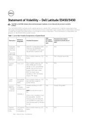
... in system kbit (64 KB), Graphics BIOS system BIOS. System memory size will depend on System Board Reference Description Designator Volatility Description User Accessible for external data Remedial Action (Action necessary to avoid the problem. Confidential N/A Part of Volatility - JDIMM1,2 One to retain their data immediately after power is removed from the component. Internal Use - Video BIOS System Memory - The Dell E5450/5450 contains both volatile and non...
... in system kbit (64 KB), Graphics BIOS system BIOS. System memory size will depend on System Board Reference Description Designator Volatility Description User Accessible for external data Remedial Action (Action necessary to avoid the problem. Confidential N/A Part of Volatility - JDIMM1,2 One to retain their data immediately after power is removed from the component. Internal Use - Video BIOS System Memory - The Dell E5450/5450 contains both volatile and non...

Dell /5450 Statement of Volatility
Page 2
.... - Dell - vPro, Intel ME firmware for vPro and non- one May also be SSD (solid state flash drive). AMD® is a registered trademark of system memory. Citrix®, Xen®, XenServer® and XenMotion® are registered trademarks of data) RTC CMOS - Secondary power loss (removing the on-board coin-cell battery) destroys system data on the memory (DDR3, 1067 MHz). Internal Use...
.... - Dell - vPro, Intel ME firmware for vPro and non- one May also be SSD (solid state flash drive). AMD® is a registered trademark of system memory. Citrix®, Xen®, XenServer® and XenMotion® are registered trademarks of data) RTC CMOS - Secondary power loss (removing the on-board coin-cell battery) destroys system data on the memory (DDR3, 1067 MHz). Internal Use...


