User Manual
Page 10
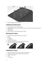
...Camera 1. Installing the Camera 1. Install: a) display bezel 10 5. Remove the screw that secures the camera and microphone module. 3. Tighten the screw that secures the camera and microphone module. 5. Follow the procedures in Before Working Inside Your Computer. 2. Connect the camera cable. 4. Follow the... procedures in After Working Inside Your Computer. Place the camera and microphone module in position on the display bezel and work around the entire bezel until it snaps onto the display assembly. 3. ...
...Camera 1. Installing the Camera 1. Install: a) display bezel 10 5. Remove the screw that secures the camera and microphone module. 3. Tighten the screw that secures the camera and microphone module. 5. Follow the procedures in Before Working Inside Your Computer. 2. Connect the camera cable. 4. Follow the... procedures in After Working Inside Your Computer. Place the camera and microphone module in position on the display bezel and work around the entire bezel until it snaps onto the display assembly. 3. ...
User Manual
Page 51
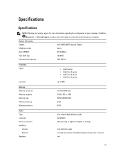
... information regarding the configuration of your computer, click Start (Start icon) → Help and Support, and then select the option to -analog) high definition audio microphone-in/stereo headphones/external speakers connector two 51
... information regarding the configuration of your computer, click Start (Start icon) → Help and Support, and then select the option to -analog) high definition audio microphone-in/stereo headphones/external speakers connector two 51

User Manual
Page 52
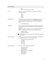
... (SIM) port Display Type Latitude E5430 Latitude E5530 Size Latitude E5430 Latitude E5530 Dimensions: 52 1W (RMS) per channel keyboard function keys, program menus integrated on system board Intel HD Graphics 10/100/1000 Mb/s Ethernet (RJ-45) internal wireless local area network (WLAN) and wireless wide area network (WWAN) one microphone/stereo headphone/speakers connector •...
... (SIM) port Display Type Latitude E5430 Latitude E5530 Size Latitude E5430 Latitude E5530 Dimensions: 52 1W (RMS) per channel keyboard function keys, program menus integrated on system board Intel HD Graphics 10/100/1000 Mb/s Ethernet (RJ-45) internal wireless local area network (WLAN) and wireless wide area network (WWAN) one microphone/stereo headphone/speakers connector •...
User Manual
Page 61
... port is enabled, device attached to this port is 100% Allows you to enable or disable the following devices: • Enable Internal Modem • Enable Microphone • Enable eSATA Ports • Enable Hard Drive Free Fall Protection • Enable Fixed Bay • Enable Express card • Enable Camera 61 This field...
... port is enabled, device attached to this port is 100% Allows you to enable or disable the following devices: • Enable Internal Modem • Enable Microphone • Enable eSATA Ports • Enable Hard Drive Free Fall Protection • Enable Fixed Bay • Enable Express card • Enable Camera 61 This field...
Setup and Features Information Tech Sheet
Page 1
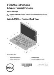
microphone (optional) 2. Dell Latitude E5430/E5530 Setup and Features Information About Warnings WARNING: A WARNING indicates a potential for property damage, personal injury, or death. Front View 1. Latitude E5430 - camera (optional) 4. camera status light (optional) Regulatory Model: P27G, P28G Regulatory Type: P27G001, P28G001 2011 - 09 Front And Back View Figure 1. display release latch 3.
microphone (optional) 2. Dell Latitude E5430/E5530 Setup and Features Information About Warnings WARNING: A WARNING indicates a potential for property damage, personal injury, or death. Front View 1. Latitude E5430 - camera (optional) 4. camera status light (optional) Regulatory Model: P27G, P28G Regulatory Type: P27G001, P28G001 2011 - 09 Front And Back View Figure 1. display release latch 3.
Setup and Features Information Tech Sheet
Page 2
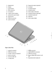
trackstick buttons (optional) 21. Back View 1. modem connector (optional) 4. security cable slot 6. USB 3.0 connector 10. ExpressCard slot (optional) 2 microphone 10. USB 2.0 connector 14. fingerprint reader (optional) 16. touchpad 17. USB 2.0 connector 3. cooling vents 7. VGA connector 9. volume control buttons 11. wireless switch 19. device status ...
trackstick buttons (optional) 21. Back View 1. modem connector (optional) 4. security cable slot 6. USB 3.0 connector 10. ExpressCard slot (optional) 2 microphone 10. USB 2.0 connector 14. fingerprint reader (optional) 16. touchpad 17. USB 2.0 connector 3. cooling vents 7. VGA connector 9. volume control buttons 11. wireless switch 19. device status ...
Setup and Features Information Tech Sheet
Page 3
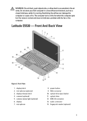
... Back View Figure 3. USB 2.0 connector 13. Fan noise is running. audio connector 14. Restricting the airflow can damage the computer or cause a fire. microphone (optional) 3. power button 9. WARNING: Do not block, push objects into, or allow dust to accumulate in a low-airflow environment, such as a ...and does not indicate a problem with the fan or the computer. optical-drive eject button 11. Do not store your Dell computer in the air vents. The computer turns on the fan when the computer gets hot. Latitude E5530 - microphone 8. fingerprint reader (optional) 3
... Back View Figure 3. USB 2.0 connector 13. Fan noise is running. audio connector 14. Restricting the airflow can damage the computer or cause a fire. microphone (optional) 3. power button 9. WARNING: Do not block, push objects into, or allow dust to accumulate in a low-airflow environment, such as a ...and does not indicate a problem with the fan or the computer. optical-drive eject button 11. Do not store your Dell computer in the air vents. The computer turns on the fan when the computer gets hot. Latitude E5530 - microphone 8. fingerprint reader (optional) 3


