User Manual
Page 2
... Removing the Camera...10 Installing the Camera...10 Removing the Display Panel...11 Installing the Display Panel...12 Removing the Keyboard Trim...12 Installing the Keyboard Trim...14 Removing the Keyboard...14 Installing the Keyboard...16 Removing the Access Panel...16 Installing the Access Panel...17 Removing the Optical Drive...17 Installing the Optical...
... Removing the Camera...10 Installing the Camera...10 Removing the Display Panel...11 Installing the Display Panel...12 Removing the Keyboard Trim...12 Installing the Keyboard Trim...14 Removing the Keyboard...14 Installing the Keyboard...16 Removing the Access Panel...16 Installing the Access Panel...17 Removing the Optical Drive...17 Installing the Optical...
User Manual
Page 12
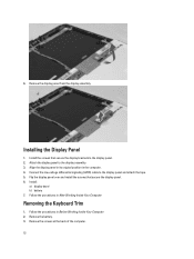
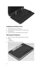
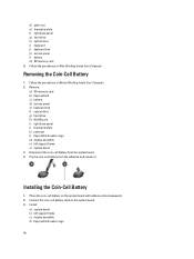
Align the display panel in its original position in Before Working Inside Your Computer. 2. Removing the Keyboard Trim 1. Follow the procedures in the computer. 4. Attach the display panel to the display panel. 2. Remove the screws at the back of the computer. 12 ...
Align the display panel in its original position in Before Working Inside Your Computer. 2. Removing the Keyboard Trim 1. Follow the procedures in the computer. 4. Attach the display panel to the display panel. 2. Remove the screws at the back of the computer. 12 ...
User Manual
Page 13
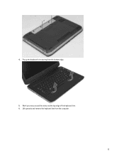
4. Pry up the keyboard trim starting from the computer. 13 Lift upwards and remove the keyboard trim from the bottom edge. 5. Work your way around the sides and the top edge of the keyboard trim. 6.
4. Pry up the keyboard trim starting from the computer. 13 Lift upwards and remove the keyboard trim from the bottom edge. 5. Work your way around the sides and the top edge of the keyboard trim. 6.
User Manual
Page 14
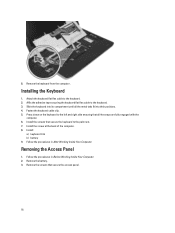
Install the battery. 4. Press along the sides of the computer. 14 Follow the procedures in After Working Inside Your Computer. Installing the Keyboard Trim 1. Follow the procedures in Before Working Inside Your Computer. 2. Remove: a) battery b) keyboard trim 3. Align the keyboard trim to its compartment. 2. Removing the Keyboard 1. Remove the screws at the back of the keyboard trim until it snaps in place. 3.
Install the battery. 4. Press along the sides of the computer. 14 Follow the procedures in After Working Inside Your Computer. Installing the Keyboard Trim 1. Follow the procedures in Before Working Inside Your Computer. 2. Remove: a) battery b) keyboard trim 3. Align the keyboard trim to its compartment. 2. Removing the Keyboard 1. Remove the screws at the back of the keyboard trim until it snaps in place. 3.

User Manual
Page 15
Flip the keyboard over. 7. Lift the clip to the back of the keyboard and remove it from the computer. 15 Remove the screws that secure the keyboard in place. 5. Peel off the adhesive tape securing the keyboard flat flex cable to release the keyboard cable and disconnect it from the computer . 6. 4.
Flip the keyboard over. 7. Lift the clip to the back of the keyboard and remove it from the computer. 15 Remove the screws that secure the keyboard in place. 5. Peel off the adhesive tape securing the keyboard flat flex cable to release the keyboard cable and disconnect it from the computer . 6. 4.
User Manual
Page 16
... compartment until all the snaps are fully engaged with the computer. 6. Install: a) keyboard trim b) battery 9. Removing the Access Panel 1. Affix the adhesive tape securing the keyboard flat flex cable to the keyboard. 2. Install the screws that secure the access panel. 16 Follow the procedures in ... Your Computer. 2. Follow the procedures in After Working Inside Your Computer. Remove the battery. 3. Remove the screws that secure the keyboard to the left and right side ensuring that all the metal tabs fit into their positions. 4. 8. Install the screw at the ...
... compartment until all the snaps are fully engaged with the computer. 6. Install: a) keyboard trim b) battery 9. Removing the Access Panel 1. Affix the adhesive tape securing the keyboard flat flex cable to the keyboard. 2. Install the screws that secure the access panel. 16 Follow the procedures in ... Your Computer. 2. Follow the procedures in After Working Inside Your Computer. Remove the battery. 3. Remove the screws that secure the keyboard to the left and right side ensuring that all the metal tabs fit into their positions. 4. 8. Install the screw at the ...
User Manual
Page 25
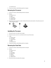
... card 4. Lift up the processor and remove it from the computer. d) SD memory card 4. Removing the Processor 1. Remove: a) SD memory card b) battery c) access panel d) keyboard trim e) keyboard f) optical drive g) right base panel 3. Follow the procedures in After Working Inside Your Computer. Follow the procedures in Before Working Inside Your Computer. 2. Installing the...
... card 4. Lift up the processor and remove it from the computer. d) SD memory card 4. Removing the Processor 1. Remove: a) SD memory card b) battery c) access panel d) keyboard trim e) keyboard f) optical drive g) right base panel 3. Follow the procedures in After Working Inside Your Computer. Follow the procedures in Before Working Inside Your Computer. 2. Installing the...
User Manual
Page 28
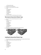
...reader cage to its original position in After Working Inside Your Computer. Remove: a) SD memory card b) battery c) access panel d) keyboard trim e) keyboard f) optical drive g) right base panel h) palmrest 3. Follow the procedures in the computer and snap it into place. 2. Follow the... procedures in place. 4. Remove the ExpressCard reader cage from the computer. Install: a) palmrest b) right base panel c) optical drive d) keyboard e) keyboard trim f) access panel g) battery 28 e) LED board flat flex cable 3. Tighten the screws at the bottom of the computer. 5. Installing...
...reader cage to its original position in After Working Inside Your Computer. Remove: a) SD memory card b) battery c) access panel d) keyboard trim e) keyboard f) optical drive g) right base panel h) palmrest 3. Follow the procedures in the computer and snap it into place. 2. Follow the... procedures in place. 4. Remove the ExpressCard reader cage from the computer. Install: a) palmrest b) right base panel c) optical drive d) keyboard e) keyboard trim f) access panel g) battery 28 e) LED board flat flex cable 3. Tighten the screws at the bottom of the computer. 5. Installing...
User Manual
Page 29
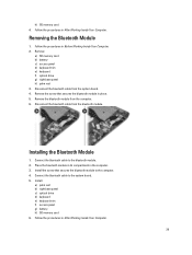
... drive g) right base panel h) palm rest 3. Install: a) palm rest b) right base panel c) optical drive d) keyboard e) keyboard trim f) access panel g) battery h) SD memory card 6. Follow the procedures in place. 5. Disconnect the bluetooth cable from the bluetooth module. Remove the screw that secures ...
... drive g) right base panel h) palm rest 3. Install: a) palm rest b) right base panel c) optical drive d) keyboard e) keyboard trim f) access panel g) battery h) SD memory card 6. Follow the procedures in place. 5. Disconnect the bluetooth cable from the bluetooth module. Remove the screw that secures ...
User Manual
Page 30
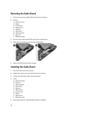
...the system board. 4. Connect the audio board cable to the computer. 3. Remove: a) SD memory card b) battery c) access panel d) keyboard trim e) keyboard f) optical drive g) right base panel h) palm rest i) bluetooth module 3. Disconnect the audio board flat flex cable from the computer. Installing ...the Audio Board 1. Install: a) bluetooth module b) palm rest c) right base panel d) optical drive e) keyboard f) keyboard trim g) access panel h) battery i) express card j) SD memory card 5. Removing the Audio Board 1. Place the audio board in place. 5....
...the system board. 4. Connect the audio board cable to the computer. 3. Remove: a) SD memory card b) battery c) access panel d) keyboard trim e) keyboard f) optical drive g) right base panel h) palm rest i) bluetooth module 3. Disconnect the audio board flat flex cable from the computer. Installing ...the Audio Board 1. Install: a) bluetooth module b) palm rest c) right base panel d) optical drive e) keyboard f) keyboard trim g) access panel h) battery i) express card j) SD memory card 5. Removing the Audio Board 1. Place the audio board in place. 5....
User Manual
Page 31
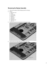
Follow the procedures in Before Working Inside Your Computer. 2. Disconnect the low-voltage differential signaling (LVDS) cable. 31 Disconnect and remove any antennae from the routing channels. 4. Removing the Display Assembly 1. Remove: a) SD memory card b) battery c) access panel d) keyboard trim e) keyboard f) optical drive g) hard drive h) right base panel i) palm rest 3.
Follow the procedures in Before Working Inside Your Computer. 2. Disconnect the low-voltage differential signaling (LVDS) cable. 31 Disconnect and remove any antennae from the routing channels. 4. Removing the Display Assembly 1. Remove: a) SD memory card b) battery c) access panel d) keyboard trim e) keyboard f) optical drive g) hard drive h) right base panel i) palm rest 3.
User Manual
Page 33
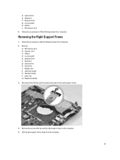
... Working Inside Your Computer. Remove the screws that secure the right support frame to the computer. 5. Remove: a) SD memory card b) express card c) battery d) access panel e) keyboard trim f) keyboard g) optical drive h) hard drive i) WLAN card j) right base panel k) thermal module l) palm rest m) display assembly 3. Disconnect the flat flex cable located at the base...
... Working Inside Your Computer. Remove the screws that secure the right support frame to the computer. 5. Remove: a) SD memory card b) express card c) battery d) access panel e) keyboard trim f) keyboard g) optical drive h) hard drive i) WLAN card j) right base panel k) thermal module l) palm rest m) display assembly 3. Disconnect the flat flex cable located at the base...
User Manual
Page 34
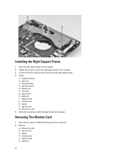
... base of the right support frame. 4. Install: a) display assembly b) palm rest c) thermal module d) right base panel e) WLAN card f) hard drive g) optical drive h) keyboard i) keyboard trim j) access panel k) battery l) express card m) SD memory card 5. Follow the procedures in After Working Inside Your Computer. Place the right support frame on the...the screws to secure the right support frame to the computer. 3. Removing The Modem Card 1. Remove: a) SD memory card b) express card c) battery d) access panel e) keyboard trim f) keyboard 34 Installing the Right Support Frame 1.
... base of the right support frame. 4. Install: a) display assembly b) palm rest c) thermal module d) right base panel e) WLAN card f) hard drive g) optical drive h) keyboard i) keyboard trim j) access panel k) battery l) express card m) SD memory card 5. Follow the procedures in After Working Inside Your Computer. Place the right support frame on the...the screws to secure the right support frame to the computer. 3. Removing The Modem Card 1. Remove: a) SD memory card b) express card c) battery d) access panel e) keyboard trim f) keyboard 34 Installing the Right Support Frame 1.
User Manual
Page 35
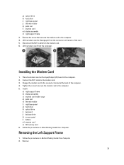
... cable from the computer. Install: a) right support frame b) display assembly c) express card reader cage d) palm rest e) thermal module f) right base panel g) hard drive h) optical drive i) keyboard j) keyboard trim k) access panel l) battery m) express card n) SD memory card 6. Remove: 35 Lift the modem card from the modem card. 6. Follow the procedures in Before Working...
... cable from the computer. Install: a) right support frame b) display assembly c) express card reader cage d) palm rest e) thermal module f) right base panel g) hard drive h) optical drive i) keyboard j) keyboard trim k) access panel l) battery m) express card n) SD memory card 6. Remove: 35 Lift the modem card from the modem card. 6. Follow the procedures in Before Working...
User Manual
Page 36
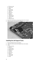
.... 4. Tighten the screws to secure the left support frame to the computer. 3. Installing the Left Support Frame 1. a) SD memory card b) express card c) battery d) access panel e) keyboard trim f) keyboard g) optical drive h) hard drive i) WLAN card j) right base panel k) thermal module l) palm rest m) display assembly 3. Lift the left support frame on the computer. 2. Install...
.... 4. Tighten the screws to secure the left support frame to the computer. 3. Installing the Left Support Frame 1. a) SD memory card b) express card c) battery d) access panel e) keyboard trim f) keyboard g) optical drive h) hard drive i) WLAN card j) right base panel k) thermal module l) palm rest m) display assembly 3. Lift the left support frame on the computer. 2. Install...
User Manual
Page 37
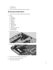
... Your Computer. Disconnect the system fan cable from the system board. 6. Disconnect the bluetooth cable. 37 l) express card m) SD memory card 4. Remove: a) battery b) access panel c) keyboard trim d) keyboard e) optical drive f) hard drive g) WLAN card h) right base panel i) thermal module j) palm rest k) express card reader cage l) display assembly m) left support frame 3. Disconnect the...
... Your Computer. Disconnect the system fan cable from the system board. 6. Disconnect the bluetooth cable. 37 l) express card m) SD memory card 4. Remove: a) battery b) access panel c) keyboard trim d) keyboard e) optical drive f) hard drive g) WLAN card h) right base panel i) thermal module j) palm rest k) express card reader cage l) display assembly m) left support frame 3. Disconnect the...
User Manual
Page 40
d) palm rest e) thermal module f) right base panel g) hard drive h) optical drive i) keyboard j) keyboard trim k) access panel l) battery m) SD memory card 5. Remove: a) SD memory card b) ExpressCard c) battery d) access panel e) keyboard trim f) optical drive g) hard drive h) WLAN card i) right base panel j) thermal module k) palmrest l) ExpressCard reader cage m) display assembly n) left support frame c) display assembly d) ExpressCard reader...
d) palm rest e) thermal module f) right base panel g) hard drive h) optical drive i) keyboard j) keyboard trim k) access panel l) battery m) SD memory card 5. Remove: a) SD memory card b) ExpressCard c) battery d) access panel e) keyboard trim f) optical drive g) hard drive h) WLAN card i) right base panel j) thermal module k) palmrest l) ExpressCard reader cage m) display assembly n) left support frame c) display assembly d) ExpressCard reader...
User Manual
Page 41
Follow the procedures in the computer. 4. Remove: a) SD memory card b) express card c) battery d) access panel e) keyboard trim f) keyboard g) optical drive h) hard drive i) WLAN card j) right base panel k) thermal module l) palm rest m) express card reader cage n) display assembly o) ... in Before Working Inside Your Computer. 2. e) palmrest f) thermal module g) right base panel h) WLAN card i) hard drive j) optical drive k) keyboard l) keyboard trim m) access panel n) battery o) ExpressCard p) SD memory card 4. Removing the Input/Output (I /O) board in After Working Inside Your Computer.
Follow the procedures in the computer. 4. Remove: a) SD memory card b) express card c) battery d) access panel e) keyboard trim f) keyboard g) optical drive h) hard drive i) WLAN card j) right base panel k) thermal module l) palm rest m) express card reader cage n) display assembly o) ... in Before Working Inside Your Computer. 2. e) palmrest f) thermal module g) right base panel h) WLAN card i) hard drive j) optical drive k) keyboard l) keyboard trim m) access panel n) battery o) ExpressCard p) SD memory card 4. Removing the Input/Output (I /O) board in After Working Inside Your Computer.
User Manual
Page 42
... board 3. Follow the procedures in After Working Inside Your Computer. Remove: a) SD memory card b) express card c) battery d) access panel e) keyboard trim f) keyboard g) optical drive h) hard drive i) WLAN card j) right base panel k) thermal module l) palm rest m) express card reader cage n) display ... express card reader cage f) palm rest g) thermal module h) right base panel i) WLAN card j) hard drive k) optical drive l) keyboard m) keyboard trim n) access panel o) battery p) express card q) SD memory card 4. Follow the procedures in Before Working Inside Your Computer. 2. Installing the ...
... board 3. Follow the procedures in After Working Inside Your Computer. Remove: a) SD memory card b) express card c) battery d) access panel e) keyboard trim f) keyboard g) optical drive h) hard drive i) WLAN card j) right base panel k) thermal module l) palm rest m) express card reader cage n) display ... express card reader cage f) palm rest g) thermal module h) right base panel i) WLAN card j) hard drive k) optical drive l) keyboard m) keyboard trim n) access panel o) battery p) express card q) SD memory card 4. Follow the procedures in Before Working Inside Your Computer. 2. Installing the ...
User Manual
Page 44
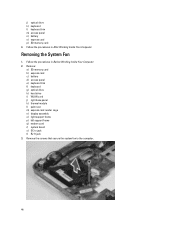
... procedures in jack t) RJ11 jack 3. Removing the System Fan 1. Remove: a) SD memory card b) express card c) battery d) access panel e) keyboard trim f) keyboard g) optical drive h) hard drive i) WLAN card j) right base panel k) thermal module l) palm rest m) express card reader cage n) display assembly...s) DC-in Before Working Inside Your Computer. 2. Follow the procedures in After Working Inside Your Computer. j) optical drive k) keyboard l) keyboard trim m) access panel n) battery o) express card p) SD memory card 4. Remove the screws that secure the system fan to the computer. 44
... procedures in jack t) RJ11 jack 3. Removing the System Fan 1. Remove: a) SD memory card b) express card c) battery d) access panel e) keyboard trim f) keyboard g) optical drive h) hard drive i) WLAN card j) right base panel k) thermal module l) palm rest m) express card reader cage n) display assembly...s) DC-in Before Working Inside Your Computer. 2. Follow the procedures in After Working Inside Your Computer. j) optical drive k) keyboard l) keyboard trim m) access panel n) battery o) express card p) SD memory card 4. Remove the screws that secure the system fan to the computer. 44


