User Manual
Page 2
... the Keyboard...14 Installing the Keyboard...16 Removing the Access Panel...16 Installing the Access Panel...17 Removing the Optical Drive...17 Installing the Optical Drive...19 Removing the Hard Drive...19 Installing the Hard Drive...21 Removing the Wireless Local Area Network (WLAN) Card 22 Installing the Wireless Local Area Network (WLAN) Card 22 Removing...
... the Keyboard...14 Installing the Keyboard...16 Removing the Access Panel...16 Installing the Access Panel...17 Removing the Optical Drive...17 Installing the Optical Drive...19 Removing the Hard Drive...19 Installing the Hard Drive...21 Removing the Wireless Local Area Network (WLAN) Card 22 Installing the Wireless Local Area Network (WLAN) Card 22 Removing...
User Manual
Page 19
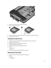
... After Working Inside Your Computer. Tighten the screws that secures the optical drive in place. 6. Disengage the optical drive bezel tabs to the optical drive. 2. Removing the Hard Drive 1. 6. Remove the screws that secure the optical drive bracket. 7. Remove the optical drive bracket. 8. Install the optical drive bracket. 3. Follow the procedures in Before Working Inside Your Computer. 2. Install...
... After Working Inside Your Computer. Tighten the screws that secures the optical drive in place. 6. Disengage the optical drive bezel tabs to the optical drive. 2. Removing the Hard Drive 1. 6. Remove the screws that secure the optical drive bracket. 7. Remove the optical drive bracket. 8. Install the optical drive bracket. 3. Follow the procedures in Before Working Inside Your Computer. 2. Install...

User Manual
Page 20
Remove the hard drive from its connector. 5. Use the tab to pull the hard drive bracket to release the hard drive from the computer. 20 3. Remove the screws that secure the hard drive bracket in place. 4.
Remove the hard drive from its connector. 5. Use the tab to pull the hard drive bracket to release the hard drive from the computer. 20 3. Remove the screws that secure the hard drive bracket in place. 4.

User Manual
Page 21
Remove the hard drive bracket from the hard drive. Install: a) access panel b) battery 6. Follow the procedures in place. 5. Remove the screws that secure the hard drive bracket. 3. Tighten the screws that secure the hard drive bracket. 7. Install the hard drive into the computer. 4. Engage the hard drive bracket to the hard drive. 2. Installing the Hard Drive 1. Tighten the screw that secures the hard drive bracket in After Working Inside Your Computer. 21 6.
Remove the hard drive bracket from the hard drive. Install: a) access panel b) battery 6. Follow the procedures in place. 5. Remove the screws that secure the hard drive bracket. 3. Tighten the screws that secure the hard drive bracket. 7. Install the hard drive into the computer. 4. Engage the hard drive bracket to the hard drive. 2. Installing the Hard Drive 1. Tighten the screw that secures the hard drive bracket in After Working Inside Your Computer. 21 6.
User Manual
Page 31
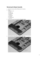
Disconnect and remove any antennae from the routing channels. 4. Disconnect the low-voltage differential signaling (LVDS) cable. 31 Remove: a) SD memory card b) battery c) access panel d) keyboard trim e) keyboard f) optical drive g) hard drive h) right base panel i) palm rest 3. Removing the Display Assembly 1. Follow the procedures in Before Working Inside Your Computer. 2.
Disconnect and remove any antennae from the routing channels. 4. Disconnect the low-voltage differential signaling (LVDS) cable. 31 Remove: a) SD memory card b) battery c) access panel d) keyboard trim e) keyboard f) optical drive g) hard drive h) right base panel i) palm rest 3. Removing the Display Assembly 1. Follow the procedures in Before Working Inside Your Computer. 2.

User Manual
Page 32
5. Install: a) palm rest b) right base panel c) hard drive 32 Pull the antennas through the holes on the chassis. 3. Install the screws that secure the display assembly in place. 2. Route the LVDS cable along ...
5. Install: a) palm rest b) right base panel c) hard drive 32 Pull the antennas through the holes on the chassis. 3. Install the screws that secure the display assembly in place. 2. Route the LVDS cable along ...
User Manual
Page 33
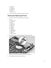
d) optical drive e) keyboard f) keyboard trim g) access panel h) battery i) SD memory card 6. Remove the screws that secure the right support frame to the computer. 5. Removing the Right Support ... support frame. 4. Lift the right support frame away from the computer. 33 Remove: a) SD memory card b) express card c) battery d) access panel e) keyboard trim f) keyboard g) optical drive h) hard drive i) WLAN card j) right base panel k) thermal module l) palm rest m) display assembly 3. Follow the procedures in Before Working Inside Your Computer. 2.
d) optical drive e) keyboard f) keyboard trim g) access panel h) battery i) SD memory card 6. Remove the screws that secure the right support frame to the computer. 5. Removing the Right Support ... support frame. 4. Lift the right support frame away from the computer. 33 Remove: a) SD memory card b) express card c) battery d) access panel e) keyboard trim f) keyboard g) optical drive h) hard drive i) WLAN card j) right base panel k) thermal module l) palm rest m) display assembly 3. Follow the procedures in Before Working Inside Your Computer. 2.
User Manual
Page 34
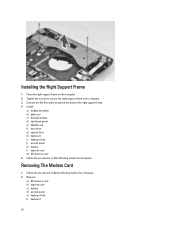
... e) keyboard trim f) keyboard 34 Place the right support frame on the computer. 2. Install: a) display assembly b) palm rest c) thermal module d) right base panel e) WLAN card f) hard drive g) optical drive h) keyboard i) keyboard trim j) access panel k) battery l) express card m) SD memory card 5. Connect the flat flex cable located at the base of the right support frame...
... e) keyboard trim f) keyboard 34 Place the right support frame on the computer. 2. Install: a) display assembly b) palm rest c) thermal module d) right base panel e) WLAN card f) hard drive g) optical drive h) keyboard i) keyboard trim j) access panel k) battery l) express card m) SD memory card 5. Connect the flat flex cable located at the base of the right support frame...
User Manual
Page 35
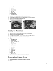
g) optical drive h) hard drive i) right base panel j) thermal module k) palm rest l) express card m) display assembly n) right support frame 3. Tighten the screw to secure the modem card to the ...card on the back of the computer. 4. Install: a) right support frame b) display assembly c) express card reader cage d) palm rest e) thermal module f) right base panel g) hard drive h) optical drive i) keyboard j) keyboard trim k) access panel l) battery m) express card n) SD memory card 6. Follow the procedures in After Working Inside Your Computer. Installing the Modem Card 1. ...
g) optical drive h) hard drive i) right base panel j) thermal module k) palm rest l) express card m) display assembly n) right support frame 3. Tighten the screw to secure the modem card to the ...card on the back of the computer. 4. Install: a) right support frame b) display assembly c) express card reader cage d) palm rest e) thermal module f) right base panel g) hard drive h) optical drive i) keyboard j) keyboard trim k) access panel l) battery m) express card n) SD memory card 6. Follow the procedures in After Working Inside Your Computer. Installing the Modem Card 1. ...
User Manual
Page 36
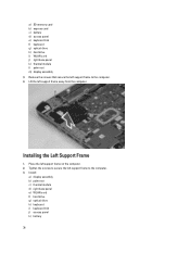
a) SD memory card b) express card c) battery d) access panel e) keyboard trim f) keyboard g) optical drive h) hard drive i) WLAN card j) right base panel k) thermal module l) palm rest m) display assembly 3. Installing the Left Support Frame 1. Lift the left support frame to the computer. 4. Remove ... the left support frame to secure the left support frame on the computer. 2. Install: a) display assembly b) palm rest c) thermal module d) right base panel e) WLAN card f) hard drive g) optical drive h) keyboard i) keyboard trim j) access panel k) battery 36
a) SD memory card b) express card c) battery d) access panel e) keyboard trim f) keyboard g) optical drive h) hard drive i) WLAN card j) right base panel k) thermal module l) palm rest m) display assembly 3. Installing the Left Support Frame 1. Lift the left support frame to the computer. 4. Remove ... the left support frame to secure the left support frame on the computer. 2. Install: a) display assembly b) palm rest c) thermal module d) right base panel e) WLAN card f) hard drive g) optical drive h) keyboard i) keyboard trim j) access panel k) battery 36
User Manual
Page 37
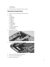
... After Working Inside Your Computer. Removing the System Board 1. Disconnect the speaker cable from the system board. 5. Remove: a) battery b) access panel c) keyboard trim d) keyboard e) optical drive f) hard drive g) WLAN card h) right base panel i) thermal module j) palm rest k) express card reader cage l) display assembly m) left support frame 3. Follow the procedures in Before Working Inside...
... After Working Inside Your Computer. Removing the System Board 1. Disconnect the speaker cable from the system board. 5. Remove: a) battery b) access panel c) keyboard trim d) keyboard e) optical drive f) hard drive g) WLAN card h) right base panel i) thermal module j) palm rest k) express card reader cage l) display assembly m) left support frame 3. Follow the procedures in Before Working Inside...
User Manual
Page 40
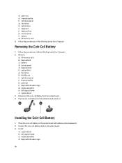
d) palm rest e) thermal module f) right base panel g) hard drive h) optical drive i) keyboard j) keyboard trim k) access panel l) battery m) SD memory card 5. Pry the coin-cell battery from the system board. 4. Place...downwards. 2. Connect the coin-cell battery cable to the system board. 3. Remove: a) SD memory card b) ExpressCard c) battery d) access panel e) keyboard trim f) optical drive g) hard drive h) WLAN card i) right base panel j) thermal module k) palmrest l) ExpressCard reader cage m) display assembly n) left support frame c) display assembly d) ExpressCard reader cage 40 ...
d) palm rest e) thermal module f) right base panel g) hard drive h) optical drive i) keyboard j) keyboard trim k) access panel l) battery m) SD memory card 5. Pry the coin-cell battery from the system board. 4. Place...downwards. 2. Connect the coin-cell battery cable to the system board. 3. Remove: a) SD memory card b) ExpressCard c) battery d) access panel e) keyboard trim f) optical drive g) hard drive h) WLAN card i) right base panel j) thermal module k) palmrest l) ExpressCard reader cage m) display assembly n) left support frame c) display assembly d) ExpressCard reader cage 40 ...
User Manual
Page 41
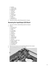
... the Input/Output (I /O) board in the computer. 4. Remove: a) SD memory card b) express card c) battery d) access panel e) keyboard trim f) keyboard g) optical drive h) hard drive i) WLAN card j) right base panel k) thermal module l) palm rest m) express card reader cage n) display assembly o) right support frame p) left support frame q) system ... Follow the procedures in After Working Inside Your Computer. e) palmrest f) thermal module g) right base panel h) WLAN card i) hard drive j) optical drive k) keyboard l) keyboard trim m) access panel n) battery o) ExpressCard p) SD memory card 4.
... the Input/Output (I /O) board in the computer. 4. Remove: a) SD memory card b) express card c) battery d) access panel e) keyboard trim f) keyboard g) optical drive h) hard drive i) WLAN card j) right base panel k) thermal module l) palm rest m) express card reader cage n) display assembly o) right support frame p) left support frame q) system ... Follow the procedures in After Working Inside Your Computer. e) palmrest f) thermal module g) right base panel h) WLAN card i) hard drive j) optical drive k) keyboard l) keyboard trim m) access panel n) battery o) ExpressCard p) SD memory card 4.
User Manual
Page 42
...Input/Output (I /O) Board 1. Remove: a) SD memory card b) express card c) battery d) access panel e) keyboard trim f) keyboard g) optical drive h) hard drive i) WLAN card j) right base panel k) thermal module l) palm rest m) express card reader cage n) display assembly o) left support frame c) right... support frame d) display assembly e) express card reader cage f) palm rest g) thermal module h) right base panel i) WLAN card j) hard drive k) optical drive l) keyboard m) keyboard trim n) access panel o) battery p) express card q) SD memory card 4. Follow the procedures in Before Working ...
...Input/Output (I /O) Board 1. Remove: a) SD memory card b) express card c) battery d) access panel e) keyboard trim f) keyboard g) optical drive h) hard drive i) WLAN card j) right base panel k) thermal module l) palm rest m) express card reader cage n) display assembly o) left support frame c) right... support frame d) display assembly e) express card reader cage f) palm rest g) thermal module h) right base panel i) WLAN card j) hard drive k) optical drive l) keyboard m) keyboard trim n) access panel o) battery p) express card q) SD memory card 4. Follow the procedures in Before Working ...

User Manual
Page 43
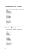
Install the DC-in jack in the routing channel. 3. Thread the DC-in cable in the computer. 2. Install: a) system board b) left support bracket c) display assembly d) express card reader cage e) palm rest f) thermal module g) right base panel h) WLAN card i) hard drive 43 4. Installing the DC-in -jack. Remove the DC-in Jack 1.
Install the DC-in jack in the routing channel. 3. Thread the DC-in cable in the computer. 2. Install: a) system board b) left support bracket c) display assembly d) express card reader cage e) palm rest f) thermal module g) right base panel h) WLAN card i) hard drive 43 4. Installing the DC-in -jack. Remove the DC-in Jack 1.
User Manual
Page 44
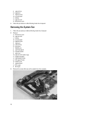
Removing the System Fan 1. Remove: a) SD memory card b) express card c) battery d) access panel e) keyboard trim f) keyboard g) optical drive h) hard drive i) WLAN card j) right base panel k) thermal module l) palm rest m) express card reader cage n) display assembly o) right support frame p) left support frame q) modem card r) system ... RJ11 jack 3. Remove the screws that secure the system fan to the computer. 44 Follow the procedures in After Working Inside Your Computer. j) optical drive k) keyboard l) keyboard trim m) access panel n) battery o) express card p) SD memory card 4.
Removing the System Fan 1. Remove: a) SD memory card b) express card c) battery d) access panel e) keyboard trim f) keyboard g) optical drive h) hard drive i) WLAN card j) right base panel k) thermal module l) palm rest m) express card reader cage n) display assembly o) right support frame p) left support frame q) modem card r) system ... RJ11 jack 3. Remove the screws that secure the system fan to the computer. 44 Follow the procedures in After Working Inside Your Computer. j) optical drive k) keyboard l) keyboard trim m) access panel n) battery o) express card p) SD memory card 4.

User Manual
Page 45
Follow the procedures in the computer. 3. 4. Installing the System Fan 1. Tighten the screws to secure the fan in After Working Inside Your Computer. 45 Lift the system fan out of the computer. Place the system fan in -jack c) system board d) modem card e) left support frame f) right support frame g) display assembly h) express card reader cage i) palm rest j) thermal module k) right base panel l) WLAN card m) hard drive n) optical drive o) keyboard p) keyboard trim q) access panel r) battery s) express card t) SD memory card 4. Install: a) RJ11 jack b) DC-in the computer. 2.
Follow the procedures in the computer. 3. 4. Installing the System Fan 1. Tighten the screws to secure the fan in After Working Inside Your Computer. 45 Lift the system fan out of the computer. Place the system fan in -jack c) system board d) modem card e) left support frame f) right support frame g) display assembly h) express card reader cage i) palm rest j) thermal module k) right base panel l) WLAN card m) hard drive n) optical drive o) keyboard p) keyboard trim q) access panel r) battery s) express card t) SD memory card 4. Install: a) RJ11 jack b) DC-in the computer. 2.
User Manual
Page 46
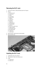
... jack. Installing the RJ11 Jack 1. Thread the RJ11 cable in the computer. 2. Remove: a) SD memory card b) express card c) battery d) access panel e) keyboard trim f) keyboard g) optical drive h) hard drive i) WLAN card j) right base panel k) thermal module l) palm rest m) express card reader cage n) display assembly o) right support frame p) left support frame q) modem card r) system board...
... jack. Installing the RJ11 Jack 1. Thread the RJ11 cable in the computer. 2. Remove: a) SD memory card b) express card c) battery d) access panel e) keyboard trim f) keyboard g) optical drive h) hard drive i) WLAN card j) right base panel k) thermal module l) palm rest m) express card reader cage n) display assembly o) right support frame p) left support frame q) modem card r) system board...

User Manual
Page 47
...Working Inside Your Computer. 2. Remove: a) SD memory card b) express card c) battery d) access panel e) keyboard trim f) keyboard g) optical drive h) hard drive i) WLAN card j) right base panel k) thermal module l) palm rest m) express card reader cage n) bluetooth module o) audio board p) LCD ...d) right support frame e) display assembly f) express card reader cage g) palm rest h) thermal module i) right base panel j) WLAN card k) hard drive l) optical drive m) keyboard n) keyboard trim o) access panel p) battery q) express card r) SD memory card 4. c) left support frame r) system board ...
...Working Inside Your Computer. 2. Remove: a) SD memory card b) express card c) battery d) access panel e) keyboard trim f) keyboard g) optical drive h) hard drive i) WLAN card j) right base panel k) thermal module l) palm rest m) express card reader cage n) bluetooth module o) audio board p) LCD ...d) right support frame e) display assembly f) express card reader cage g) palm rest h) thermal module i) right base panel j) WLAN card k) hard drive l) optical drive m) keyboard n) keyboard trim o) access panel p) battery q) express card r) SD memory card 4. c) left support frame r) system board ...

User Manual
Page 49
g) palm rest h) thermal module i) right base panel j) WLAN card k) hard drive l) optical drive m) keyboard n) keyboard trim o) access panel p) battery q) express card r) SD memory card 5. Follow the procedures in After Working Inside Your Computer. 49
g) palm rest h) thermal module i) right base panel j) WLAN card k) hard drive l) optical drive m) keyboard n) keyboard trim o) access panel p) battery q) express card r) SD memory card 5. Follow the procedures in After Working Inside Your Computer. 49


