Dell Latitude E5430 Support Question
Dell Latitude E5430 Support Question
Find answers below for this question about Dell Latitude E5430.Need a Dell Latitude E5430 manual? We have 3 online manuals for this item!
Question posted by daniejp on June 24th, 2014
How To Replace Hard Drive Dell Latitude E5430
The person who posted this question about this Dell product did not include a detailed explanation. Please use the "Request More Information" button to the right if more details would help you to answer this question.
Current Answers
Related Dell Latitude E5430 Manual Pages
User Manual - Page 2
... the Keyboard...14 Installing the Keyboard...16 Removing the Access Panel...16 Installing the Access Panel...17 Removing the Optical Drive...17 Installing the Optical Drive...19 Removing the Hard Drive...19 Installing the Hard Drive...21 Removing the Wireless Local Area Network (WLAN) Card 22 Installing the Wireless Local Area Network (WLAN) Card 22 Removing...
User Manual - Page 19
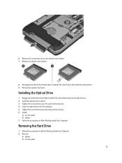
... bezel tabs to attach the optical drive bezel to separate the optical drive bezel from the optical drive. 9. Insert the optical drive into the computer. 5. Install the optical drive bracket. 3. Removing the Hard Drive
1. Tighten the screws that secure the optical drive bracket. 7. Install:
a) access panel b) battery 7.
Follow the procedures in place. 6. 6. Remove the screws...
User Manual - Page 20

Use the tab to pull the hard drive bracket to release the hard drive from the computer. 20 3. Remove the screws that secure the hard drive bracket in place. 4. Remove the hard drive from its connector. 5.
User Manual - Page 21

... the screws that secure the hard drive bracket.
7. Installing the Hard Drive
1. Tighten the screw that secures the hard drive bracket in After Working Inside Your Computer.
21 Remove the screws that secure the hard drive bracket. 3. Remove the hard drive bracket from the hard drive. 6. Engage the hard drive bracket to the hard drive. 2. Install:
a) access panel b) battery 6. Follow...
User Manual - Page 31
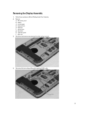
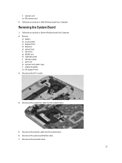
Follow the procedures in Before Working Inside Your Computer. 2. Remove:
a) SD memory card b) battery c) access panel d) keyboard trim e) keyboard f) optical drive g) hard drive h) right base panel i) palm rest 3. Disconnect the low-voltage differential signaling (LVDS) cable.
31 Removing the Display Assembly
1. Disconnect and remove any antennae from the routing channels.
4.
User Manual - Page 32

Installing the Display Assembly
1. Install the screws that secure the display assembly in place. 2. Install:
a) palm rest b) right base panel c) hard drive 32 5. Connect the antenna cables to the system board. 4. Remove the screws that secures the display assembly in place.
7.
Insert the low-voltage differential signaling (...
User Manual - Page 33
...card b) express card c) battery d) access panel e) keyboard trim f) keyboard g) optical drive h) hard drive i) WLAN card j) right base panel k) thermal module l) palm rest m) display assembly ...frame.
4. Follow the procedures in After Working Inside Your Computer. d) optical drive e) keyboard f) keyboard trim g) access panel h) battery i) SD memory card 6. Follow the procedures in Before Working...
User Manual - Page 34
... SD memory card b) express card c) battery d) access panel e) keyboard trim f) keyboard
34 Install:
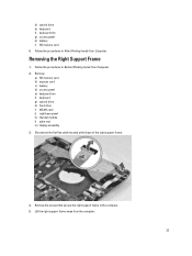
a) display assembly b) palm rest c) thermal module d) right base panel e) WLAN card f) hard drive g) optical drive h) keyboard i) keyboard trim j) access panel k) battery l) express card m) SD memory card 5. Tighten the screws to secure the right support frame to the computer. 3.
Removing The...
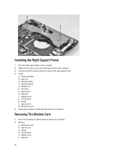
User Manual - Page 35
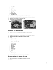
... card n) SD memory card 6. Disconnect the RJ11 cable from the computer. Lift the modem card from the modem card. 6. Removing the Left Support Frame
1. g) optical drive h) hard drive i) right base panel j) thermal module k) palm rest l) express card m) display assembly n) right support frame 3.
Connect the RJ11 cable to the computer. 5. Follow the procedures in...
User Manual - Page 36
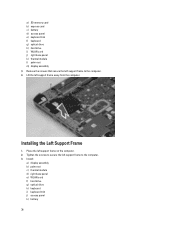
... support frame on the computer. 2. Place the left support frame to the computer. 4. a) SD memory card b) express card c) battery d) access panel e) keyboard trim f) keyboard g) optical drive h) hard drive i) WLAN card j) right base panel k) thermal module l) palm rest m) display assembly 3. Lift the left support frame to secure the left support frame away from the...
User Manual - Page 37
... system board.
5. Disconnect the DC-in Before Working Inside Your Computer. 2. Follow the procedures in cable.
4. Remove:
a) battery b) access panel c) keyboard trim d) keyboard e) optical drive f) hard drive g) WLAN card h) right base panel i) thermal module j) palm rest k) express card reader cage l) display assembly m) left support frame 3. Disconnect the audio board flat flex cable...
User Manual - Page 40
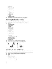
...the Coin-Cell Battery
1. Connect the coin-cell battery cable to the system board. 3. Remove:
a) SD memory card b) ExpressCard c) battery d) access panel e) keyboard trim f) optical drive g) hard drive h) WLAN card i) right base panel j) thermal module k) palmrest l) ExpressCard reader cage m) display assembly n) left support frame c) display assembly d) ExpressCard reader cage
40 d) palm rest...
User Manual - Page 41
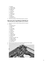
...rest m) express card reader cage n) display assembly o) right support frame p) left support frame q) system board 3. e) palmrest f) thermal module g) right base panel h) WLAN card i) hard drive j) optical drive k) keyboard l) keyboard trim m) access panel n) battery o) ExpressCard p) SD memory card 4. Remove the screws that secure the Input/Output (I /O) Board
1. Follow the procedures in Before...
User Manual - Page 42
... cage n) display assembly o) left support frame c) right support frame d) display assembly e) express card reader cage f) palm rest g) thermal module h) right base panel i) WLAN card j) hard drive k) optical drive l) keyboard m) keyboard trim n) access panel o) battery p) express card q) SD memory card
4. Remove the DC-in After Working Inside Your Computer. Tighten the screw to the...
User Manual - Page 43

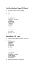
Thread the DC-in cable in -jack. Install:
a) system board b) left support bracket c) display assembly d) express card reader cage e) palm rest f) thermal module g) right base panel h) WLAN card i) hard drive
43 Remove the DC-in the routing channel. 3. Installing the DC-in the computer. 2. Install the DC-in jack in Jack
1. 4.
User Manual - Page 59

...L2 Cache, Processor L3 Cache, HT Capable, and 64-Bit Technology.
• Device Information: Displays Primary Hard Drive, Fixed bay Device, System eSATA Device, Dock eSATA Device, LOM MAC Address, Video Controller, Video BIOS Version..., or remove any hardware in this section may or may not appear. When the blue DELL logo is displayed, you must watch for the F2 prompt to wait until you see the...
Setup and Features Information Tech Sheet - Page 1
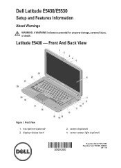
microphone (optional) 2. Latitude E5430 -
Front View
1. display release latch
3. Front And Back View
Figure 1. Dell Latitude E5430/E5530
Setup and Features Information
About Warnings
WARNING: A WARNING indicates a potential for property damage, personal injury, or death. camera (optional) 4. camera status light (optional)
Regulatory ...
Setup and Features Information Tech Sheet - Page 7

... Operating Temperature:
Latitude E5430 / E5530
0 °C to 35 °C (32 °F to change without the written permission of these materials in this publication is subject to 95 °F)
Finding More Information and Resources
See the safety and regulatory documents that shipped with your product is strictly forbidden.
7
Reproduction of Dell Inc. is available...
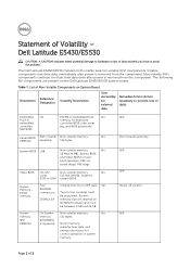
Statement of Volatility - Page 1
...
No
cards
512 kbit (64 KB), Graphics
(G92 or G94) system BIOS.
The Dell Latitude E5430/E5530 contains both volatile and non-volatile (NV) components.
Four SODIMM connectors:
JDIM1,2,3,4
Volatile...avoid the problem. System memory size will depend on
board diags), PXE diags. Dell Latitude E5430/E5530
CAUTION: A CAUTION indicates either potential damage to prevent loss of data)
...
Statement of Volatility - Page 2
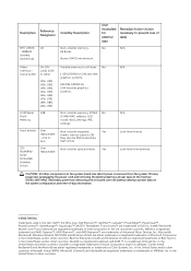
..., U5A, U5B, U6A, U6B, U7A, U7B, U8A, U8B, U9A, U9B
LOM Serial U18 Flash Memory
Hard drive(s)
User replaceable - Trademarks used in the United States and other countries. in this text: Dell™, the DELL logo, Dell Precision™, OptiPlex™, Latitude™, PowerEdge™, PowerVault™, PowerConnect™, OpenManage™, EqualLogic™, KACE™, FlexAddress™...
Similar Questions


Dell Latitude E5430 Wireless Switch
dell latitude E5430 does not find any wireless networks. msg says to make sure wireless switch is on...
dell latitude E5430 does not find any wireless networks. msg says to make sure wireless switch is on...
(Posted by mwosbon 10 years ago)

How To Replace Hard Drive In Dell Inspiron N5050
(Posted by ssatyJorg 10 years ago)
How Can I Fix Hard Drive Pipee Voice And Giving Me Msg Hard Not Installed
(Posted by engmkhalifa 11 years ago)