User Manual
Page 2
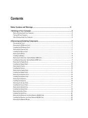
... Access Panel...17 Removing the Optical Drive...17 Installing the Optical Drive...19 Removing the Hard Drive...19 Installing the Hard Drive...21 Removing the Wireless Local Area Network (WLAN) Card 22 Installing the Wireless Local Area Network (WLAN) Card 22 Removing the Memory Module...22
... Access Panel...17 Removing the Optical Drive...17 Installing the Optical Drive...19 Removing the Hard Drive...19 Installing the Hard Drive...21 Removing the Wireless Local Area Network (WLAN) Card 22 Installing the Wireless Local Area Network (WLAN) Card 22 Removing the Memory Module...22

User Manual
Page 22
... Press the clips to secure the memory module to the computer. 4. Follow the procedures in After Working Inside Your Computer. Installing the Wireless Local Area Network (WLAN) Card 1. Follow the procedures in Before Working Inside Your Computer. 2. Pry the retention clips away from the...antennae cables from its slot on the WLAN card. 3. Insert the WLAN card into its slot. 2. Installing the Memory Module 1. Removing the Wireless Local Area Network (WLAN) Card 1. Remove the screw that secures the WLAN card to their respective connectors marked on the system board. Removing...
... Press the clips to secure the memory module to the computer. 4. Follow the procedures in After Working Inside Your Computer. Installing the Wireless Local Area Network (WLAN) Card 1. Follow the procedures in Before Working Inside Your Computer. 2. Pry the retention clips away from the...antennae cables from its slot on the WLAN card. 3. Insert the WLAN card into its slot. 2. Installing the Memory Module 1. Removing the Wireless Local Area Network (WLAN) Card 1. Remove the screw that secures the WLAN card to their respective connectors marked on the system board. Removing...

User Manual
Page 32
Remove the screws that secures the display assembly in place. 7. Insert the low-voltage differential signaling (LVDS) cable and wireless antennae cables through the opening to the top of the computer. 6. Remove the display assembly from the computer. Installing the Display Assembly 1. Install the screws ...
Remove the screws that secures the display assembly in place. 7. Insert the low-voltage differential signaling (LVDS) cable and wireless antennae cables through the opening to the top of the computer. 6. Remove the display assembly from the computer. Installing the Display Assembly 1. Install the screws ...

User Manual
Page 52
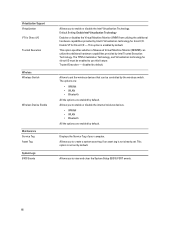
Audio Internal speaker amplifier Volume controls Video Type Controller Communications Network adapter Wireless Ports and Connectors Audio (optional) Video Network adapter USB 2.0 USB 3.0 Memory card reader Docking port Subscriber Identity Module (SIM) port Display Type Latitude E5430 Latitude E5530 Size Latitude E5430 Latitude E5530 Dimensions: 52 1W (RMS) per channel keyboard function keys, program menus integrated on system...
Audio Internal speaker amplifier Volume controls Video Type Controller Communications Network adapter Wireless Ports and Connectors Audio (optional) Video Network adapter USB 2.0 USB 3.0 Memory card reader Docking port Subscriber Identity Module (SIM) port Display Type Latitude E5430 Latitude E5530 Size Latitude E5430 Latitude E5530 Dimensions: 52 1W (RMS) per channel keyboard function keys, program menus integrated on system...

User Manual
Page 64
...Default Setting: Enable USB Wake Support is not selected Allows you to enable or disable the feature that automatically switches from wired or wireless networks without depending on the physical connection. • Control WLAN Radio • Control WWAN Radio • Default Setting: Control WLAN.... • Disabled: This option is connected. Performance Hyper-Thread Control Power Management AC Behavior Auto On Time USB Wake Support Wireless Radio Control Wake on LAN/WLAN Block Sleep Primary Battery Configuration Default Setting: Enable Intel TurboBoost Allows you to enable or disable ...
...Default Setting: Enable USB Wake Support is not selected Allows you to enable or disable the feature that automatically switches from wired or wireless networks without depending on the physical connection. • Control WLAN Radio • Control WWAN Radio • Default Setting: Control WLAN.... • Disabled: This option is connected. Performance Hyper-Thread Control Power Management AC Behavior Auto On Time USB Wake Support Wireless Radio Control Wake on LAN/WLAN Block Sleep Primary Battery Configuration Default Setting: Enable Intel TurboBoost Allows you to enable or disable ...
User Manual
Page 66
...Monitor (MVMM) can be enabled to enable or disable the Intel Virtualization Technology. Enable VT for Direct I/O Trusted Execution Wireless Wireless Switch Wireless Device Enable Maintenance Service Tag Asset Tag System Logs BIOS Events Allows you to enable or disable the internal...options are enabled by Intel® Virtualization technology for direct I/O must be controlled by default. This option is not already set the wireless devices that can utilize the additional hardware capabilities provided by default. disabled by default. Allows you to use this feature. Allows to ...
...Monitor (MVMM) can be enabled to enable or disable the Intel Virtualization Technology. Enable VT for Direct I/O Trusted Execution Wireless Wireless Switch Wireless Device Enable Maintenance Service Tag Asset Tag System Logs BIOS Events Allows you to enable or disable the internal...options are enabled by Intel® Virtualization technology for direct I/O must be controlled by default. This option is not already set the wireless devices that can utilize the additional hardware capabilities provided by default. disabled by default. Allows you to use this feature. Allows to ...

User Manual
Page 67
Turns on when wireless networking is enabled. Temporary battery failure with AC adapter present. Battery Status Lights If the computer is connected to an electrical outlet, the battery light ... blue light Alternately blinking amber light with steady blue light Constantly blinking amber light Light off Solid white light on An unauthenticated or unsupported non-Dell AC adapter is attached to indicate battery charge status. Fatal battery failure with AC adapter present. Diagnostics Diagnostics Device Status Lights Turns on when you...
Turns on when wireless networking is enabled. Temporary battery failure with AC adapter present. Battery Status Lights If the computer is connected to an electrical outlet, the battery light ... blue light Alternately blinking amber light with steady blue light Constantly blinking amber light Light off Solid white light on An unauthenticated or unsupported non-Dell AC adapter is attached to indicate battery charge status. Fatal battery failure with AC adapter present. Diagnostics Diagnostics Device Status Lights Turns on when you...
Setup and Features Information Tech Sheet
Page 2
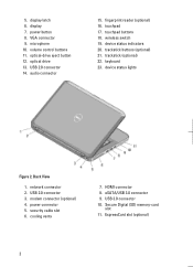
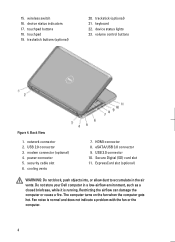
... slot 11. ExpressCard slot (optional) 2 display latch 6. USB 2.0 connector 14. device status indicators 20. power connector 5. security cable slot 6. eSATA/USB 3.0 connector 9. optical drive 13. wireless switch 19. Back View 1. USB 2.0 connector 3. cooling vents 7. USB 3.0 connector 10. VGA connector 9. keyboard 23. optical-drive eject button 12. 5. display 7. fingerprint reader (optional) 16...
... slot 11. ExpressCard slot (optional) 2 display latch 6. USB 2.0 connector 14. device status indicators 20. power connector 5. security cable slot 6. eSATA/USB 3.0 connector 9. optical drive 13. wireless switch 19. Back View 1. USB 2.0 connector 3. cooling vents 7. USB 3.0 connector 10. VGA connector 9. keyboard 23. optical-drive eject button 12. 5. display 7. fingerprint reader (optional) 16...
Setup and Features Information Tech Sheet
Page 4
... 9. Restricting the airflow can damage the computer or cause a fire. keyboard 22. USB 2.0 connector 3. cooling vents 7. Do not store your Dell computer in the air vents. touchpad buttons 18. trackstick (optional) 21. security cable slot 6. Secure Digital (SD) card slot 11. network ... environment, such as a closed briefcase, while it is normal and does not indicate a problem with the fan or the computer. 4 wireless switch 16. trackstick buttons (optional) 20. device status indicators 17. power connector 5. modem connector (optional) 4. The computer turns on ...
... 9. Restricting the airflow can damage the computer or cause a fire. keyboard 22. USB 2.0 connector 3. cooling vents 7. Do not store your Dell computer in the air vents. touchpad buttons 18. trackstick (optional) 21. security cable slot 6. Secure Digital (SD) card slot 11. network ... environment, such as a closed briefcase, while it is normal and does not indicate a problem with the fan or the computer. 4 wireless switch 16. trackstick buttons (optional) 20. device status indicators 17. power connector 5. modem connector (optional) 4. The computer turns on ...

Setup and Features Information Tech Sheet
Page 8
...proprietary interest in the U.S. Other trademarks and trade names may be used in this text: Dell™, the DELL logo, Dell Precision™, Precision ON™, ExpressCharge™, Latitude™, Latitude ON™, OptiPlex™, Vostro™, and Wi-Fi Catcher™ are either the entities... Devices, Inc. is a registered trademark and owned by the Blu-ray Disc Association (BDA) and licensed for use of Wireless Ethernet Compatibility Alliance, Inc. Trademarks used in this publication to refer to either trademarks or registered trademarks of Microsoft Corporation in...
...proprietary interest in the U.S. Other trademarks and trade names may be used in this text: Dell™, the DELL logo, Dell Precision™, Precision ON™, ExpressCharge™, Latitude™, Latitude ON™, OptiPlex™, Vostro™, and Wi-Fi Catcher™ are either the entities... Devices, Inc. is a registered trademark and owned by the Blu-ray Disc Association (BDA) and licensed for use of Wireless Ethernet Compatibility Alliance, Inc. Trademarks used in this publication to refer to either trademarks or registered trademarks of Microsoft Corporation in...


