
Service Manual
Page 8
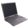
...provides instructions for removing and replacing field-replaceable components, assemblies, and subassemblies in Figure 1 unless otherwise specified. The angle of computer support.dell.com Dell Latitude CPt V/CPt S Series and CPx H/CPx J Series Service Manual 1 back of computer left side right side front of the display assembly with respect to the bottom case should never be..., when performing the procedures in this manual assumes that you use a book or something similar to the computer are as shown in your Dell Latitude portable computer. It is open nearly 180 degrees.
...provides instructions for removing and replacing field-replaceable components, assemblies, and subassemblies in Figure 1 unless otherwise specified. The angle of computer support.dell.com Dell Latitude CPt V/CPt S Series and CPx H/CPx J Series Service Manual 1 back of computer left side right side front of the display assembly with respect to the bottom case should never be..., when performing the procedures in this manual assumes that you use a book or something similar to the computer are as shown in your Dell Latitude portable computer. It is open nearly 180 degrees.

Service Manual
Page 9
... Port Replicator (APR), undock the computer. 4. If the computer is turned off the computer and any installed devices in the modular device bay. 2 Dell Latitude CPt V/CPt S Series and CPx H/CPx J Series Service Manual Remove any attached peripherals. Remove any work in this manual require the following tools: Number 1 magnetized Phillips-head screwdriver Small flat-blade...
... Port Replicator (APR), undock the computer. 4. If the computer is turned off the computer and any installed devices in the modular device bay. 2 Dell Latitude CPt V/CPt S Series and CPx H/CPx J Series Service Manual Remove any attached peripherals. Remove any work in this manual require the following tools: Number 1 magnetized Phillips-head screwdriver Small flat-blade...

Service Manual
Page 10
M2.5x20 M2.5x10 M3.0x5 M2.5x4 M2.5x4 M3.0x3 M2.0x3 support.dell.com Dell Latitude CPt V/CPt S Series and CPx H/CPx J Series Service Manual 3 The illustrations in Figure 3. Ground yourself by touching the unpainted metal surface of the I /O panel to dissipate any static electricity that length screw ...
M2.5x20 M2.5x10 M3.0x5 M2.5x4 M2.5x4 M3.0x3 M2.0x3 support.dell.com Dell Latitude CPt V/CPt S Series and CPx H/CPx J Series Service Manual 3 The illustrations in Figure 3. Ground yourself by touching the unpainted metal surface of the I /O panel to dissipate any static electricity that length screw ...

Service Manual
Page 11
.... When you are removing and replacing components, photocopy the Table 1 placement mat as a tool to your system) Thermal Cooling Assembly and Exhaust Fan: M2.5 x 4 (2 each) 4 Dell Latitude CPt V/CPt S Series and CPx H/CPx J Series Service Manual
.... When you are removing and replacing components, photocopy the Table 1 placement mat as a tool to your system) Thermal Cooling Assembly and Exhaust Fan: M2.5 x 4 (2 each) 4 Dell Latitude CPt V/CPt S Series and CPx H/CPx J Series Service Manual

Service Manual
Page 12
... connector. 2. Grasp the interface cable and pull it releases the interface cable. 3. While holding the cable in place, close the ZIF connector. support.dell.com Dell Latitude CPt V/CPt S Series and CPx H/CPx J Series Service Manual 5 Some of connector (do not remove) 1. Orient the end of the interface cable with the ZIF connector, and insert the end...
... connector. 2. Grasp the interface cable and pull it releases the interface cable. 3. While holding the cable in place, close the ZIF connector. support.dell.com Dell Latitude CPt V/CPt S Series and CPx H/CPx J Series Service Manual 5 Some of connector (do not remove) 1. Orient the end of the interface cable with the ZIF connector, and insert the end...

Service Manual
Page 13
... these parts and assemblies. Some parts may only be available as part of a service kit or assembly and are provided for the manufacturer's name. 6 Dell Latitude CPt V/CPt S Series and CPx H/CPx J Series Service Manual CUS, ADPT, AC, EXT, 20V, 70W, NBK ADPT, AC, EXT, 20V, 70W, 3W, BA CORD, PWR, 110V, 6F, ...AC, 3W/3P, US Customer kit, main battery CUS, BTRY, 14.4V, 8CELL, LITH 2 CUS, BTRY, 9.6V, 8CELL, NiMH (option for CPt S-Series only) Main battery ...
... these parts and assemblies. Some parts may only be available as part of a service kit or assembly and are provided for the manufacturer's name. 6 Dell Latitude CPt V/CPt S Series and CPx H/CPx J Series Service Manual CUS, ADPT, AC, EXT, 20V, 70W, NBK ADPT, AC, EXT, 20V, 70W, 3W, BA CORD, PWR, 110V, 6F, ...AC, 3W/3P, US Customer kit, main battery CUS, BTRY, 14.4V, 8CELL, LITH 2 CUS, BTRY, 9.6V, 8CELL, NiMH (option for CPt S-Series only) Main battery ...

Service Manual
Page 14
... 14.1-inch flex cable ASSY, CBL, FLX, TFT 12.1-inch flex cable ASSY, CBL, FLX, W/EXTN,12.1 14 14 16 16 14 16, 17 support.dell.com Dell Latitude CPt V/CPt S Series and CPx H/CPx J Series Service Manual 7
... 14.1-inch flex cable ASSY, CBL, FLX, TFT 12.1-inch flex cable ASSY, CBL, FLX, W/EXTN,12.1 14 14 16 16 14 16, 17 support.dell.com Dell Latitude CPt V/CPt S Series and CPx H/CPx J Series Service Manual 7

Service Manual
Page 15
...-MB CUS, 128MB, DIMM, SDRAM Customer kit, memory module, 192-MB CUS, 192MB, DIMM, SDRAM Customer kit, memory module, 256-MB CUS, 256MB, DIMM, SDRAM 8 Dell Latitude CPt V/CPt S Series and CPx H/CPx J Series Service Manual
...-MB CUS, 128MB, DIMM, SDRAM Customer kit, memory module, 192-MB CUS, 192MB, DIMM, SDRAM Customer kit, memory module, 256-MB CUS, 256MB, DIMM, SDRAM 8 Dell Latitude CPt V/CPt S Series and CPx H/CPx J Series Service Manual

Service Manual
Page 16
... Kit, latch, slider, Button Foot, Rubber, Black (4 each) Foot, Rubber, Strike Zone, Black LTCH, BTN, Module Foot, Rbr, Blk Foot, Rbr, Strike Zone, Blk support.dell.com Dell Latitude CPt V/CPt S Series and CPx H/CPx J Series Service Manual 9
... Kit, latch, slider, Button Foot, Rubber, Black (4 each) Foot, Rubber, Strike Zone, Black LTCH, BTN, Module Foot, Rbr, Blk Foot, Rbr, Strike Zone, Blk support.dell.com Dell Latitude CPt V/CPt S Series and CPx H/CPx J Series Service Manual 9

Service Manual
Page 17
display assembly keyboard palmrest assembly hard-disk drive internal modem (may not apply to your system) system board main battery case plug for modem bottom case assembly modular bay device The following subsections provide instructions for removing and replacing field-replaceable parts and assemblies. 10 Dell Latitude CPt V/CPt S Series and CPx H/CPx J Series Service Manual
display assembly keyboard palmrest assembly hard-disk drive internal modem (may not apply to your system) system board main battery case plug for modem bottom case assembly modular bay device The following subsections provide instructions for removing and replacing field-replaceable parts and assemblies. 10 Dell Latitude CPt V/CPt S Series and CPx H/CPx J Series Service Manual

Service Manual
Page 18
... computer. 1. Slide the drive door up and pull the drive assembly out of computer 5-mm screw M3.0x5 hard-disk drive door 1. support.dell.com Dell Latitude CPt V/CPt S Series and CPx H/CPx J Series Service Manual 11 Turn the computer over , and remove the 5-mm screw from the center of the computer. 2. Turn the computer over and...
... computer. 1. Slide the drive door up and pull the drive assembly out of computer 5-mm screw M3.0x5 hard-disk drive door 1. support.dell.com Dell Latitude CPt V/CPt S Series and CPx H/CPx J Series Service Manual 11 Turn the computer over , and remove the 5-mm screw from the center of the computer. 2. Turn the computer over and...

Service Manual
Page 19
... the memory module cover. latch lock 1. Insert a flat-blade screwdriver under the indentation in the bottom case assembly and lift the cover. 12 Dell Latitude CPt V/CPt S Series and CPx H/CPx J Series Service Manual Keep holding the latch open while pulling the device out of the modular bay with the other hand (see Figure 7). 1. Push the...
... the memory module cover. latch lock 1. Insert a flat-blade screwdriver under the indentation in the bottom case assembly and lift the cover. 12 Dell Latitude CPt V/CPt S Series and CPx H/CPx J Series Service Manual Keep holding the latch open while pulling the device out of the modular bay with the other hand (see Figure 7). 1. Push the...

Service Manual
Page 20
... present). 2. Remove the memory module cover. 3. they are designed for the memory module to fit into their sockets, in the DIMM A socket. support.dell.com Dell Latitude CPt V/CPt S Series and CPx H/CPx J Series Service Manual 13 Be sure that the memory module can be firmly seated only one direction. inner tabs (2 per socket) memory module sockets...
... present). 2. Remove the memory module cover. 3. they are designed for the memory module to fit into their sockets, in the DIMM A socket. support.dell.com Dell Latitude CPt V/CPt S Series and CPx H/CPx J Series Service Manual 13 Be sure that the memory module can be firmly seated only one direction. inner tabs (2 per socket) memory module sockets...

Service Manual
Page 21
... display assembly, and turn the computer upside down until it . 4. Pivot the memory module down on a flat work surface. 10-mm screws (7) M2.5x10 14 Dell Latitude CPt V/CPt S Series and CPx H/CPx J Series Service Manual 2. Remove the main battery and secondary battery (if present). 2.
... display assembly, and turn the computer upside down until it . 4. Pivot the memory module down on a flat work surface. 10-mm screws (7) M2.5x10 14 Dell Latitude CPt V/CPt S Series and CPx H/CPx J Series Service Manual 2. Remove the main battery and secondary battery (if present). 2.

Service Manual
Page 22
Rotate the keyboard over the left side of the computer. support.dell.com Dell Latitude CPt V/CPt S Series and CPx H/CPx J Series Service Manual 15 Release the keyboard from the palmrest assembly by inserting a small flat-blade screwdriver under the edge of the blank key (see Figure ...
Rotate the keyboard over the left side of the computer. support.dell.com Dell Latitude CPt V/CPt S Series and CPx H/CPx J Series Service Manual 15 Release the keyboard from the palmrest assembly by inserting a small flat-blade screwdriver under the edge of the blank key (see Figure ...

Service Manual
Page 23
... that the contact side of the computer with the keys face down when you insert the cable into the keyboard ZIF interface connector. 16 Dell Latitude CPt V/CPt S Series and CPx H/CPx J Series Service Manual Connect the keyboard cable to the ZIF connector. Disconnect the keyboard cable from the ZIF connector on the system board. track...
... that the contact side of the computer with the keys face down when you insert the cable into the keyboard ZIF interface connector. 16 Dell Latitude CPt V/CPt S Series and CPx H/CPx J Series Service Manual Connect the keyboard cable to the ZIF connector. Disconnect the keyboard cable from the ZIF connector on the system board. track...

Service Manual
Page 24
Ensure that the keyboard is correctly installed. Carefully turn the keyboard over and reinstall the seven 10-mm screws. support.dell.com Dell Latitude CPt V/CPt S Series and CPx H/CPx J Series Service Manual 17 The keys should be flush with the left and right sides of the palmrest. 7. To push the keyboard down, press on the ...
Ensure that the keyboard is correctly installed. Carefully turn the keyboard over and reinstall the seven 10-mm screws. support.dell.com Dell Latitude CPt V/CPt S Series and CPx H/CPx J Series Service Manual 17 The keys should be flush with the left and right sides of the palmrest. 7. To push the keyboard down, press on the ...

Service Manual
Page 25
... screw (1) shield brace (may not apply to your system) white marks on the microprocessor shield securing the thermal cooling assembly to the microprocessor module. 18 Dell Latitude CPt V/CPt S Series and CPx H/CPx J Series Service Manual Remove the keyboard assembly. 3. Remove the main battery and secondary battery (if present). 2.
... screw (1) shield brace (may not apply to your system) white marks on the microprocessor shield securing the thermal cooling assembly to the microprocessor module. 18 Dell Latitude CPt V/CPt S Series and CPx H/CPx J Series Service Manual Remove the keyboard assembly. 3. Remove the main battery and secondary battery (if present). 2.

Service Manual
Page 26
... left side of the board and press down firmly on the front and back edge of the processor board (see Figure 12). 1. support.dell.com Dell Latitude CPt V/CPt S Series and CPx H/CPx J Series Service Manual 19 Use a microprocessor extractor tool to remove the microprocessor module. When the microprocessor module is directly over the corner without the...
... left side of the board and press down firmly on the front and back edge of the processor board (see Figure 12). 1. support.dell.com Dell Latitude CPt V/CPt S Series and CPx H/CPx J Series Service Manual 19 Use a microprocessor extractor tool to remove the microprocessor module. When the microprocessor module is directly over the corner without the...

Service Manual
Page 27
... the display assembly from the back of the computer (see Figure 13). NOTE: Always remove and replace the LCD panel as a complete assembly. 20 Dell Latitude CPt V/CPt S Series and CPx H/CPx J Series Service Manual Remove the keyboard. 3. display assembly hinge cover LCD flex cable snap tab bottom case assembly 4-mm screws (3) snap tab M2.5x4 1.
... the display assembly from the back of the computer (see Figure 13). NOTE: Always remove and replace the LCD panel as a complete assembly. 20 Dell Latitude CPt V/CPt S Series and CPx H/CPx J Series Service Manual Remove the keyboard. 3. display assembly hinge cover LCD flex cable snap tab bottom case assembly 4-mm screws (3) snap tab M2.5x4 1.


