

Service Manual
Page 15
... Customer kit, memory CUS, 32MB, DIMM, SDRAM 8 module, 32-MB Customer kit, memory module, 64-MB CUS, 64MB, DIMM, SDRAM Customer kit, memory module, 128-MB CUS, 128MB, DIMM, SDRAM Customer kit, memory module, 192-MB CUS, 192MB, DIMM, SDRAM Customer kit, memory module, 256-MB CUS, 256MB, DIMM, SDRAM 8 Dell Latitude CPt V/CPt S Series and CPx H/CPx J Series Service Manual
... Customer kit, memory CUS, 32MB, DIMM, SDRAM 8 module, 32-MB Customer kit, memory module, 64-MB CUS, 64MB, DIMM, SDRAM Customer kit, memory module, 128-MB CUS, 128MB, DIMM, SDRAM Customer kit, memory module, 192-MB CUS, 192MB, DIMM, SDRAM Customer kit, memory module, 256-MB CUS, 256MB, DIMM, SDRAM 8 Dell Latitude CPt V/CPt S Series and CPx H/CPx J Series Service Manual

Service Manual
Page 16
Memory door assembly DOOR, MEM, MET, NB System board assembly, SVCKIT, MB ASSY, PWA, ENGINE 22 service kit Service tag installation diskette DSK, BIOS, FLDSVC, F3, ... Kit, latch, slider, Button Foot, Rubber, Black (4 each) Foot, Rubber, Strike Zone, Black LTCH, BTN, Module Foot, Rbr, Blk Foot, Rbr, Strike Zone, Blk support.dell.com Dell Latitude CPt V/CPt S Series and CPx H/CPx J Series Service Manual 9
Memory door assembly DOOR, MEM, MET, NB System board assembly, SVCKIT, MB ASSY, PWA, ENGINE 22 service kit Service tag installation diskette DSK, BIOS, FLDSVC, F3, ... Kit, latch, slider, Button Foot, Rubber, Black (4 each) Foot, Rubber, Strike Zone, Black LTCH, BTN, Module Foot, Rbr, Blk Foot, Rbr, Strike Zone, Blk support.dell.com Dell Latitude CPt V/CPt S Series and CPx H/CPx J Series Service Manual 9

Service Manual
Page 19
... in the bottom case assembly and lift the cover. 12 Dell Latitude CPt V/CPt S Series and CPx H/CPx J Series Service Manual latch lock 1. Push the module latch toward the unlock icon. Close the display, and turn the computer upside down on a flat work surface. 3. Release the memory module cover. Keep holding the latch open while pulling the...
... in the bottom case assembly and lift the cover. 12 Dell Latitude CPt V/CPt S Series and CPx H/CPx J Series Service Manual latch lock 1. Push the module latch toward the unlock icon. Close the display, and turn the computer upside down on a flat work surface. 3. Release the memory module cover. Keep holding the latch open while pulling the...

Service Manual
Page 20
... the socket. The module should pop up slightly (see Figure 8). 4. support.dell.com Dell Latitude CPt V/CPt S Series and CPx H/CPx J Series Service Manual 13 To release a memory module from its socket. 1. Lift the memory module out of its socket, carefully spread apart the inner tabs of the memory module socket just far enough for either the socket labeled DIMM...
... the socket. The module should pop up slightly (see Figure 8). 4. support.dell.com Dell Latitude CPt V/CPt S Series and CPx H/CPx J Series Service Manual 13 To release a memory module from its socket. 1. Lift the memory module out of its socket, carefully spread apart the inner tabs of the memory module socket just far enough for either the socket labeled DIMM...

Service Manual
Page 21
...1. If you do not hear a click as each end of the memory module socket. Pivot the memory module down on a flat work surface. 10-mm screws (7) M2.5x10 14 Dell Latitude CPt V/CPt S Series and CPx H/CPx J Series Service Manual Close the display assembly, and turn the computer upside down until... it . 4. 2. Remove the main battery and secondary battery (if present). 2. Align the memory module's edge connector with the slot ...
...1. If you do not hear a click as each end of the memory module socket. Pivot the memory module down on a flat work surface. 10-mm screws (7) M2.5x10 14 Dell Latitude CPt V/CPt S Series and CPx H/CPx J Series Service Manual Close the display assembly, and turn the computer upside down until... it . 4. 2. Remove the main battery and secondary battery (if present). 2. Align the memory module's edge connector with the slot ...
Service Manual
Page 42
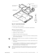
...assembly out of the replacement system board assembly. Follow the instructions on the computer. support.dell.com Dell Latitude CPt V/CPt S Series and CPx H/CPx J Series Service Manual 35 Insert the diskette (or CD-ROM) that accompanied the replacement system board... assembly into the BIOS of the bottom case assembly. 1. Replace the system board mounting screws. 4. Replace the modem (if present). 3. NOTE: Be sure to transfer the memory...
...assembly out of the replacement system board assembly. Follow the instructions on the computer. support.dell.com Dell Latitude CPt V/CPt S Series and CPx H/CPx J Series Service Manual 35 Insert the diskette (or CD-ROM) that accompanied the replacement system board... assembly into the BIOS of the bottom case assembly. 1. Replace the system board mounting screws. 4. Replace the modem (if present). 3. NOTE: Be sure to transfer the memory...
Service Manual
Page 47
..., 18 modular bay devices removal, 12 module latch assemblies removal, 37 screw identification and tightening, 3 sockets memory module, 13 SuperDisk LS-120 drive removal, 12 system board assembly removal, 18 thermal cooling assembly removal, 36 tools, 2 travel module removal, 12 ZIF connectors, 5 palmrest assembly removal, 30 2 Dell Latitude CPt V/CPt S Series and CPx H/Cpx J Series Service Manual
..., 18 modular bay devices removal, 12 module latch assemblies removal, 37 screw identification and tightening, 3 sockets memory module, 13 SuperDisk LS-120 drive removal, 12 system board assembly removal, 18 thermal cooling assembly removal, 36 tools, 2 travel module removal, 12 ZIF connectors, 5 palmrest assembly removal, 30 2 Dell Latitude CPt V/CPt S Series and CPx H/Cpx J Series Service Manual


