
Service Manual
Page 7
Replacing the LED Board 5 2 Fan Assembly 5 2 Removing the Fan Assembly 5 2 RJ-11/RJ-45 Board 5 3 Removing the Protective Covers From the RJ-11 and RJ-45 Connectors 5 3 Removing the RJ-11/RJ-45 Board 5 4 Index 5 7 5
Replacing the LED Board 5 2 Fan Assembly 5 2 Removing the Fan Assembly 5 2 RJ-11/RJ-45 Board 5 3 Removing the Protective Covers From the RJ-11 and RJ-45 Connectors 5 3 Removing the RJ-11/RJ-45 Board 5 4 Index 5 7 5

Service Manual
Page 13
...: M2.5 x 20 mm (9 each) System Board: M2.5 x 4 mm captive washer (3 each) LED Board: M2.0 x 4 mm (2 each) Palmrest Bracket: M2.5 x 4 mm (2 each) M2.5 x 20 mm (1 each) Fan Assembly: M2.0 x 4 mm (3 each) RJ-11/RJ-45 Board Assembly: M2.5 x 4 mm (1 each ;
...: M2.5 x 20 mm (9 each) System Board: M2.5 x 4 mm captive washer (3 each) LED Board: M2.0 x 4 mm (2 each) Palmrest Bracket: M2.5 x 4 mm (2 each) M2.5 x 20 mm (1 each) Fan Assembly: M2.0 x 4 mm (3 each) RJ-11/RJ-45 Board Assembly: M2.5 x 4 mm (1 each ;
Service Manual
Page 15
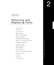
SECTION 2 Removing and Replacing Parts System Components Hard Drive Fixed Optical Drive Memory Module Mini PCI Card Assembly Keyboard Assembly Display and Bezel Assemblies Microprocessor Thermal Cooling Assembly Microprocessor Module Video Graphics Board Palmrest Assembly Reserve Battery System Board Assembly Battery and Modular Bay Latch Assemblies Battery Charger Board LED Board Fan Assembly RJ-11/RJ-45 Board www.dell.com | support.dell.com 2
SECTION 2 Removing and Replacing Parts System Components Hard Drive Fixed Optical Drive Memory Module Mini PCI Card Assembly Keyboard Assembly Display and Bezel Assemblies Microprocessor Thermal Cooling Assembly Microprocessor Module Video Graphics Board Palmrest Assembly Reserve Battery System Board Assembly Battery and Modular Bay Latch Assemblies Battery Charger Board LED Board Fan Assembly RJ-11/RJ-45 Board www.dell.com | support.dell.com 2

Service Manual
Page 54
... instructions in "Preparing to Work Inside the Computer." 2 Remove the system board. 3 Remove the three 4-mm screws from the fan assembly. 4 Disconnect the two fan cables from electrical outlets and remove any installed batteries. Fan Assembly NOTICE: Disconnect the computer and attached devices from the system board. 52 Rem o vi n g an d Rep l a ci...
... instructions in "Preparing to Work Inside the Computer." 2 Remove the system board. 3 Remove the three 4-mm screws from the fan assembly. 4 Disconnect the two fan cables from electrical outlets and remove any installed batteries. Fan Assembly NOTICE: Disconnect the computer and attached devices from the system board. 52 Rem o vi n g an d Rep l a ci...

Service Manual
Page 55
...yourself by using a wrist grounding strap or by slipping a nonmarring tool into the cutout at the top and pivoting the tool up to the fan assembly. RJ-11 and RJ-45 Connector Covers connector covers (2) Removing the Protective Covers From the RJ-11 and RJ-45 Connectors Remove a plastic... connector cover (if necessary) by periodically touching unpainted metal on the computer. 5 Pull the fan assembly away from electrical outlets and remove any installed batteries. RJ-11/RJ-45 Board NOTICE: Disconnect the computer and attached devices from the back...
...yourself by using a wrist grounding strap or by slipping a nonmarring tool into the cutout at the top and pivoting the tool up to the fan assembly. RJ-11 and RJ-45 Connector Covers connector covers (2) Removing the Protective Covers From the RJ-11 and RJ-45 Connectors Remove a plastic... connector cover (if necessary) by periodically touching unpainted metal on the computer. 5 Pull the fan assembly away from electrical outlets and remove any installed batteries. RJ-11/RJ-45 Board NOTICE: Disconnect the computer and attached devices from the back...

Service Manual
Page 59
... display assembly bezel, 30 display assembly bezel and panel (illustrated), 30 display flex cable, 29, 32 display latch, 33 display panel removing, 31 replacing, 32 F fan assembly, 52 fixed optical drive, 16 flex cable display, 29, 32 palmrest, 43 H hard drive removing, 16 replacing, 16 hinge cover, 27 microprocessor thermal cooling...
... display assembly bezel, 30 display assembly bezel and panel (illustrated), 30 display flex cable, 29, 32 display latch, 33 display panel removing, 31 replacing, 32 F fan assembly, 52 fixed optical drive, 16 flex cable display, 29, 32 palmrest, 43 H hard drive removing, 16 replacing, 16 hinge cover, 27 microprocessor thermal cooling...
System Information Guide
Page 13
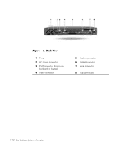
Figure 1-6. Back View 1 Fans 2 AC power connector 3 PS/2 connector (for mouse, keyboard, or keypad) 4 Video connector 5 Docking connector 6 Parallel connector 7 Serial connector 8 USB connectors 1-10 Dell Latitude System Information
Figure 1-6. Back View 1 Fans 2 AC power connector 3 PS/2 connector (for mouse, keyboard, or keypad) 4 Video connector 5 Docking connector 6 Parallel connector 7 Serial connector 8 USB connectors 1-10 Dell Latitude System Information


