Service Manual
Page 5
... to Work Inside the Computer 8 Recommended Tools 9 Screw Identification 1 0 2 Removing and Replacing Parts System Components 1 4 Hard Drive 1 5 Removing the Hard Drive 1 6 Replacing the Hard Drive 1 6 Fixed Optical Drive 1 6 Removing the Fixed Optical Drive 1 7 Memory Module 1 7 Removing the Memory Module Cover 1 7 Removing the Memory Modules 1 8 Replacing the Memory Modules 1 8 Mini PCI Card Assembly 1 9 Removing the Mini PCI Card Assembly 2 0 Replacing the Mini PCI Card Assembly 2 1 Keyboard Assembly 2 2 Removing the Keyboard Assembly 2 3 Replacing the Keyboard Assembly...
... to Work Inside the Computer 8 Recommended Tools 9 Screw Identification 1 0 2 Removing and Replacing Parts System Components 1 4 Hard Drive 1 5 Removing the Hard Drive 1 6 Replacing the Hard Drive 1 6 Fixed Optical Drive 1 6 Removing the Fixed Optical Drive 1 7 Memory Module 1 7 Removing the Memory Module Cover 1 7 Removing the Memory Modules 1 8 Replacing the Memory Modules 1 8 Mini PCI Card Assembly 1 9 Removing the Mini PCI Card Assembly 2 0 Replacing the Mini PCI Card Assembly 2 1 Keyboard Assembly 2 2 Removing the Keyboard Assembly 2 3 Replacing the Keyboard Assembly...
Service Manual
Page 6
...6 Removing the Hinge Cover 2 7 Removing the Display Assembly 2 8 Removing the Display Assembly Bezel 3 0 Removing the Display Panel 3 1 Replacing the Display Panel 3 2 Removing the Display Latch 3 3 Microprocessor Thermal Cooling Assembly 3 4 Removing the Microprocessor Thermal Cooling Assembly . . . 3 4 Microprocessor Module 3 5 Removing the Microprocessor Module 3 6 Replacing the Microprocessor Module 3 7 Video Graphics Board 3 8 Removing the Video Graphics Board 3 9 Replacing the Video Graphics Board 3 9 Palmrest Assembly 4 0 Removing the Palmrest Assembly 4 1 Reserve Battery...
...6 Removing the Hinge Cover 2 7 Removing the Display Assembly 2 8 Removing the Display Assembly Bezel 3 0 Removing the Display Panel 3 1 Replacing the Display Panel 3 2 Removing the Display Latch 3 3 Microprocessor Thermal Cooling Assembly 3 4 Removing the Microprocessor Thermal Cooling Assembly . . . 3 4 Microprocessor Module 3 5 Removing the Microprocessor Module 3 6 Replacing the Microprocessor Module 3 7 Video Graphics Board 3 8 Removing the Video Graphics Board 3 9 Replacing the Video Graphics Board 3 9 Palmrest Assembly 4 0 Removing the Palmrest Assembly 4 1 Reserve Battery...
Service Manual
Page 10
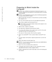
... l.co m | su p po rt. Damage due to servicing that the work surface is undocked. 5 Disconnect the computer from the battery bay. com Preparing to prevent scratching the computer cover. 2 Save any device installed in progress and close all open application programs. 3 Turn off the computer, make sure the computer is not in a power-management mode. 4 Make sure the computer is flat and clean...
... l.co m | su p po rt. Damage due to servicing that the work surface is undocked. 5 Disconnect the computer from the battery bay. com Preparing to prevent scratching the computer cover. 2 Save any device installed in progress and close all open application programs. 3 Turn off the computer, make sure the computer is not in a power-management mode. 4 Make sure the computer is flat and clean...
Service Manual
Page 15
SECTION 2 Removing and Replacing Parts System Components Hard Drive Fixed Optical Drive Memory Module Mini PCI Card Assembly Keyboard Assembly Display and Bezel Assemblies Microprocessor Thermal Cooling Assembly Microprocessor Module Video Graphics Board Palmrest Assembly Reserve Battery System Board Assembly Battery and Modular Bay Latch Assemblies Battery Charger Board LED Board Fan Assembly RJ-11/RJ-45 Board www.dell.com | support.dell.com 2
SECTION 2 Removing and Replacing Parts System Components Hard Drive Fixed Optical Drive Memory Module Mini PCI Card Assembly Keyboard Assembly Display and Bezel Assemblies Microprocessor Thermal Cooling Assembly Microprocessor Module Video Graphics Board Palmrest Assembly Reserve Battery System Board Assembly Battery and Modular Bay Latch Assemblies Battery Charger Board LED Board Fan Assembly RJ-11/RJ-45 Board www.dell.com | support.dell.com 2
Service Manual
Page 19
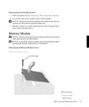
... computer. Removing the Memory Module Cover Memory Module Cover 20-mm screw Re m ov i n g a nd Re p l ac i n g Pa rt s 17 NOTICE: To avoid ESD, ground yourself by using a wrist grounding strap or by periodically touching unpainted metal on the bottom of the computer. NOTICE: To keep the pull tab from electrical outlets and remove any installed batteries. Removing the Fixed Optical Drive 1 Follow the instructions in...
... computer. Removing the Memory Module Cover Memory Module Cover 20-mm screw Re m ov i n g a nd Re p l ac i n g Pa rt s 17 NOTICE: To avoid ESD, ground yourself by using a wrist grounding strap or by periodically touching unpainted metal on the bottom of the computer. NOTICE: To keep the pull tab from electrical outlets and remove any installed batteries. Removing the Fixed Optical Drive 1 Follow the instructions in...
Service Manual
Page 20
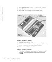
... the instructions in "Preparing to Work Inside the Computer." 2 Remove the screw. 3 Disengage the metal tabs at each side of the module until the module pops up slightly. 3 Lift the memory module out of the cover. Replacing the Memory Modules 1 If you only have one memory module, install it in the socket labeled "DIMM B." 18 Rem o vi n g an d Rep l a ci n g Pa rt s Install a second memory module in...
... the instructions in "Preparing to Work Inside the Computer." 2 Remove the screw. 3 Disengage the metal tabs at each side of the module until the module pops up slightly. 3 Lift the memory module out of the cover. Replacing the Memory Modules 1 If you only have one memory module, install it in the socket labeled "DIMM B." 18 Rem o vi n g an d Rep l a ci n g Pa rt s Install a second memory module in...
Service Manual
Page 21
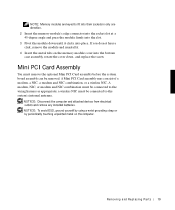
... periodically touching unpainted metal on the memory module cover into place. a wireless NIC must remove the optional Mini PCI Card assembly before the system board assembly can be connected to fit into their sockets in only one direction. 2 Insert the memory module's edge connector into the socket slot at a 45-degree angle and press the module firmly into the slot. 3 Pivot the module down , and replace the...
... periodically touching unpainted metal on the memory module cover into place. a wireless NIC must remove the optional Mini PCI Card assembly before the system board assembly can be connected to fit into their sockets in only one direction. 2 Insert the memory module's edge connector into the socket slot at a 45-degree angle and press the module firmly into the slot. 3 Pivot the module down , and replace the...

Service Manual
Page 24
.... Keyboard Assembly NOTICE: Disconnect the computer and attached devices from electrical outlets and remove any installed batteries. d ell. NOTICE: If you are installing a wireless NIC, fold and tuck the unused wiring harness into the slot so it does not interfere with the cover. 3 Pivot the Mini PCI Card assembly down until it clicks into place. 4 Replace the Mini PCI Card assembly cover. NOTICE...
.... Keyboard Assembly NOTICE: Disconnect the computer and attached devices from electrical outlets and remove any installed batteries. d ell. NOTICE: If you are installing a wireless NIC, fold and tuck the unused wiring harness into the slot so it does not interfere with the cover. 3 Pivot the Mini PCI Card assembly down until it clicks into place. 4 Replace the Mini PCI Card assembly cover. NOTICE...
Service Manual
Page 26
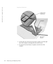
com Keyboard Removal scalloped edge of blank key keyboard right side of computer 5 Lift the right end of the keyboard and slide it slightly toward the right side of the computer to disengage the tabs at the left end. 6 Pivot the keyboard and balance it upright on the left side of the computer. 24 Rem o vi n g an d Rep l a ci n g Pa rt s w w w.d el l.co m | su p po rt. d ell.
com Keyboard Removal scalloped edge of blank key keyboard right side of computer 5 Lift the right end of the keyboard and slide it slightly toward the right side of the computer to disengage the tabs at the left end. 6 Pivot the keyboard and balance it upright on the left side of the computer. 24 Rem o vi n g an d Rep l a ci n g Pa rt s w w w.d el l.co m | su p po rt. d ell.
Service Manual
Page 34
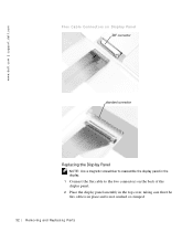
com Flex Cable Connectors on Display Panel ZIF connector standard connector Replacing the Display Panel NOTE: Use a magnetic screwdriver to reassemble the display panel in the display. 1 Connect the flex cable to the two connectors on the back of the display panel. 2 Place the display panel assembly in the top cover, taking care that the flex cable is in place and is not crushed or crimped. 32 Rem o vi n g an d Rep l a ci n g Pa rt s d ell. w w w.d el l.co m | su p po rt.
com Flex Cable Connectors on Display Panel ZIF connector standard connector Replacing the Display Panel NOTE: Use a magnetic screwdriver to reassemble the display panel in the display. 1 Connect the flex cable to the two connectors on the back of the display panel. 2 Place the display panel assembly in the top cover, taking care that the flex cable is in place and is not crushed or crimped. 32 Rem o vi n g an d Rep l a ci n g Pa rt s d ell. w w w.d el l.co m | su p po rt.

Service Manual
Page 38
..., hold the screwdriver so that it is perpendicular to Work Inside the Computer." 2 Remove the keyboard. 3 Remove the hinge cover. The location of the thermal pads. 4 Remove the microprocessor thermal cooling assembly. Do not bend the pins. 5 Remove the microprocessor module. d ell. NOTICE: To ensure maximum cooling for small icons indicating open and locked positions. 36 Rem o vi n g an d Rep l a ci n g Pa rt...
..., hold the screwdriver so that it is perpendicular to Work Inside the Computer." 2 Remove the keyboard. 3 Remove the hinge cover. The location of the thermal pads. 4 Remove the microprocessor thermal cooling assembly. Do not bend the pins. 5 Remove the microprocessor module. d ell. NOTICE: To ensure maximum cooling for small icons indicating open and locked positions. 36 Rem o vi n g an d Rep l a ci n g Pa rt...
Service Manual
Page 39
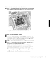
... aligned to prevent intermittent contact between the cam lock screw and microprocessor. When the microprocessor module is not properly seated can result in an intermittent connection and subsequent failures. 1 Align the pin-1 triangle on updating or reflashing the BIOS, see the Dell Portable Computer BIOS Update Guide. For instructions on the microprocessor toward the pin-1 triangle in the socket, insert...
... aligned to prevent intermittent contact between the cam lock screw and microprocessor. When the microprocessor module is not properly seated can result in an intermittent connection and subsequent failures. 1 Align the pin-1 triangle on updating or reflashing the BIOS, see the Dell Portable Computer BIOS Update Guide. For instructions on the microprocessor toward the pin-1 triangle in the socket, insert...

Service Manual
Page 48
... replacement microprocessor, you must update the BIOS after replacing the microprocessor module. com The replacement kit for the system board assembly includes a diskette or CD that provides a utility for transferring the service tag number to Work Inside the Computer." 2 Remove the hard drive and the fixed optical drive. 3 Remove any installed Mini PCI Cards. 4 If migrating the memory, remove all installed memory modules. 5 Remove the keyboard. 6 Remove the hinge cover. 7 Remove the display assembly. 8 Remove the palmrest assembly. 9 Remove the video graphics board. 10 Remove...
... replacement microprocessor, you must update the BIOS after replacing the microprocessor module. com The replacement kit for the system board assembly includes a diskette or CD that provides a utility for transferring the service tag number to Work Inside the Computer." 2 Remove the hard drive and the fixed optical drive. 3 Remove any installed Mini PCI Cards. 4 If migrating the memory, remove all installed memory modules. 5 Remove the keyboard. 6 Remove the hinge cover. 7 Remove the display assembly. 8 Remove the palmrest assembly. 9 Remove the video graphics board. 10 Remove...

System Information Guide
Page 4
... describe changes to obtain them. Dell™ Latitude™ System Information Your Dell Latitude portable computer accessories box includes a reduced set of computer features, instructions on installing and configuring drivers and utilities, information on your hard drive. This documentation includes information that are sometimes included with your computer: • The Getting Started placemat, which provides step-by-step instructions for attaching devices to configure and install these updates before...
... describe changes to obtain them. Dell™ Latitude™ System Information Your Dell Latitude portable computer accessories box includes a reduced set of computer features, instructions on installing and configuring drivers and utilities, information on your hard drive. This documentation includes information that are sometimes included with your computer: • The Getting Started placemat, which provides step-by-step instructions for attaching devices to configure and install these updates before...
System Information Guide
Page 5
... remove the grounding prong from the support site at http:// support.dell.com. With extended operation, heat can potentially build up in a wet environment, for use your computer. Use of other troubleshooting information from a cable. also, do not use the AC adapter inside a carrying case. • Do not use with this computer. Safety Instructions Use the following safety guidelines: • Do not allow your hard drive...
... remove the grounding prong from the support site at http:// support.dell.com. With extended operation, heat can potentially build up in a wet environment, for use your computer. Use of other troubleshooting information from a cable. also, do not use the AC adapter inside a carrying case. • Do not use with this computer. Safety Instructions Use the following safety guidelines: • Do not allow your hard drive...
System Information Guide
Page 6
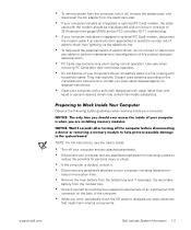
... computer. support.dell.com Dell Latitude System Information 1-3 Use care when removing PC Cards after turning off the computer before disconnecting a device or removing a memory module to help avoid the potential hazard of electric shock, do not connect or disconnect any cables or perform maintenance or reconfiguration of this product during an electrical storm. • PC Cards may become very warm during normal operation. Preparing to Work Inside...
... computer. support.dell.com Dell Latitude System Information 1-3 Use care when removing PC Cards after turning off the computer before disconnecting a device or removing a memory module to help avoid the potential hazard of electric shock, do not connect or disconnect any cables or perform maintenance or reconfiguration of this product during an electrical storm. • PC Cards may become very warm during normal operation. Preparing to Work Inside...

System Information Guide
Page 8
... 1 AC adapter 5 Cable for optional modem 2 Track stick caps 6 TV/digital audio adapter cable 3 AC adapter power cable 7 Travel module 4 Operating system documentation 8 ResourceCD support.dell.com Dell Latitude System Information 1-5 Figure 1-1. The accessories box also contains user documentation and any software or additional hardware (such as PC Cards, drives, or batteries) you will need to complete the setup of the accessories box, which you have ordered. Getting Started To set up your computer. Set aside the...
... 1 AC adapter 5 Cable for optional modem 2 Track stick caps 6 TV/digital audio adapter cable 3 AC adapter power cable 7 Travel module 4 Operating system documentation 8 ResourceCD support.dell.com Dell Latitude System Information 1-5 Figure 1-1. The accessories box also contains user documentation and any software or additional hardware (such as PC Cards, drives, or batteries) you will need to complete the setup of the accessories box, which you have ordered. Getting Started To set up your computer. Set aside the...
System Information Guide
Page 14
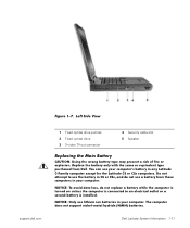
... support.dell.com 1 Fixed optical drive pull-tab 2 Fixed optical drive 3 S-video TV-out connector 4 Security cable slot 5 Speaker Replacing the Main Battery CAUTION: Using the wrong battery type may present a risk of fire or explosion. Replace the battery only with the same or equivalent type purchased from those computers in CS or CSx, and do not replace a battery while the computer is turned on unless the computer is connected to use...
... support.dell.com 1 Fixed optical drive pull-tab 2 Fixed optical drive 3 S-video TV-out connector 4 Security cable slot 5 Speaker Replacing the Main Battery CAUTION: Using the wrong battery type may present a risk of fire or explosion. Replace the battery only with the same or equivalent type purchased from those computers in CS or CSx, and do not replace a battery while the computer is turned on unless the computer is connected to use...
System Information Guide
Page 15
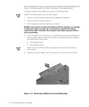
... work and close all open files and application programs. 2. Removing a Battery From the Battery Bay 1-12 Dell Latitude System Information NOTICE: If you choose to replace the battery with the computer in one of these ways. • Use suspend mode. • Use hibernate mode. If the only battery in the computer is in the battery bay, perform the following steps. NOTE: For full instructions, see your User's Guide...
... work and close all open files and application programs. 2. Removing a Battery From the Battery Bay 1-12 Dell Latitude System Information NOTICE: If you choose to replace the battery with the computer in one of these ways. • Use suspend mode. • Use hibernate mode. If the only battery in the computer is in the battery bay, perform the following steps. NOTE: For full instructions, see your User's Guide...

System Information Guide
Page 19
... Drive • Boot Third Device: Internal HDD 6. After the diagnostics loads, the Diagnostics Menu appears. NOTE: Run the diagnostics before you call . Select the following steps: 1. Then restart your needs. When you start the diagnostics, the Dell logo screen appears, followed by a message telling you that you solve it. NOTE: You can boot only from a CD-ROM, CD-RW, or DVD-ROM drive installed as a fixed optical drive...
... Drive • Boot Third Device: Internal HDD 6. After the diagnostics loads, the Diagnostics Menu appears. NOTE: Run the diagnostics before you call . Select the following steps: 1. Then restart your needs. When you start the diagnostics, the Dell logo screen appears, followed by a message telling you that you solve it. NOTE: You can boot only from a CD-ROM, CD-RW, or DVD-ROM drive installed as a fixed optical drive...


