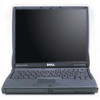
Service Manual
Page 6
... Cooling Assembly 44 Removing the Microprocessor Thermal Cooling Assembly . . . . 44 Hybrid Cooling Fan 45 Removing the Hybrid Cooling Fan 46 Microprocessor Module 47 Removing the Microprocessor Module 47 Replacing the Microprocessor Module 48 Reserve Battery 49 Removing the Reserve Battery 49 Replacing the Reserve Battery 50 Speaker Assemblies 50 Removing the Speaker Assemblies 51...
... Cooling Assembly 44 Removing the Microprocessor Thermal Cooling Assembly . . . . 44 Hybrid Cooling Fan 45 Removing the Hybrid Cooling Fan 46 Microprocessor Module 47 Removing the Microprocessor Module 47 Replacing the Microprocessor Module 48 Reserve Battery 49 Removing the Reserve Battery 49 Replacing the Reserve Battery 50 Speaker Assemblies 50 Removing the Speaker Assemblies 51...
Service Manual
Page 15
SECTION 2 Removing and Replacing Parts Components Hard Drive Memory Module Mini-PCI Card Assembly Keyboard Assembly Removing the Display Assembly Display Assembly Latch Hinge Covers Palmrest Assembly Microprocessor Thermal Cooling Assembly Hybrid Cooling Fan Microprocessor Module Reserve Battery Speaker Assemblies System Board Assembly Battery and Modular Bay Latch Assemblies www.dell.com | support.dell.com
SECTION 2 Removing and Replacing Parts Components Hard Drive Memory Module Mini-PCI Card Assembly Keyboard Assembly Removing the Display Assembly Display Assembly Latch Hinge Covers Palmrest Assembly Microprocessor Thermal Cooling Assembly Hybrid Cooling Fan Microprocessor Module Reserve Battery Speaker Assemblies System Board Assembly Battery and Modular Bay Latch Assemblies www.dell.com | support.dell.com
Service Manual
Page 16
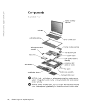
..., each procedure in reverse order. 16 Removi ng and Replacing Parts www.dell.com | support.dell.com Components Exploded View display-assembly top cover keyboard palmrest assembly center control cover left speaker/antenna assembly hard drive main battery thermal cooling assembly hybrid cooling fan system board right speaker/antenna assembly modem and NIC connector...
..., each procedure in reverse order. 16 Removi ng and Replacing Parts www.dell.com | support.dell.com Components Exploded View display-assembly top cover keyboard palmrest assembly center control cover left speaker/antenna assembly hard drive main battery thermal cooling assembly hybrid cooling fan system board right speaker/antenna assembly modem and NIC connector...
Service Manual
Page 46
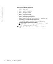
NOTICE: Do not block the keyboard screw hole when reinserting the fan cable. 46 Removi ng and Replacing Parts www.dell.com | support.dell.com Removing the Hybrid Cooling Fan 1 Remove the hard drive. 2 Remove the keyboard assembly. 3 Remove the display assembly. 4 Remove the palmrest assembly. 5 Remove the thermal cooling assembly. 6 Remove the two M2.5 x 5-...
NOTICE: Do not block the keyboard screw hole when reinserting the fan cable. 46 Removi ng and Replacing Parts www.dell.com | support.dell.com Removing the Hybrid Cooling Fan 1 Remove the hard drive. 2 Remove the keyboard assembly. 3 Remove the display assembly. 4 Remove the palmrest assembly. 5 Remove the thermal cooling assembly. 6 Remove the two M2.5 x 5-...
Service Manual
Page 54
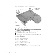
www.dell.com | support.dell.com Removing the System Board Assembly Screws fan guard M2.5 x 5-mm screws (9) Removing the System Board NOTICE: Disconnect the computer and any installed batteries. NOTICE: Read "Preparing to Work Inside the Computer" before ... all PC Cards or plastic blanks are removed from electrical outlets, and remove any attached devices from the PC Card slot. 54 Removi ng and Replacing Parts NOTICE: To avoid ESD, ground yourself by using a wrist grounding strap or by periodically touching an unpainted metal on the computer.
www.dell.com | support.dell.com Removing the System Board Assembly Screws fan guard M2.5 x 5-mm screws (9) Removing the System Board NOTICE: Disconnect the computer and any installed batteries. NOTICE: Read "Preparing to Work Inside the Computer" before ... all PC Cards or plastic blanks are removed from electrical outlets, and remove any attached devices from the PC Card slot. 54 Removi ng and Replacing Parts NOTICE: To avoid ESD, ground yourself by using a wrist grounding strap or by periodically touching an unpainted metal on the computer.
Service Manual
Page 56
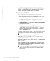
... headphone connectors through the plastic bottom case assembly. Follow the instructions on the right side of the bottom case assembly. www.dell.com | support.dell.com 13 Pull the right side of bottom case assembly, next to the external headphone and microphone connectors, away from the...: Be sure to route cables so that they will not be sure to the replacement system board. 3 Install the replacement system board. Replacing the System Board 1 Install the microprocessor on the computer. c Replace the fan guard cover, inserting the tab into the BIOS of the system board assembly out and...
... headphone connectors through the plastic bottom case assembly. Follow the instructions on the right side of the bottom case assembly. www.dell.com | support.dell.com 13 Pull the right side of bottom case assembly, next to the external headphone and microphone connectors, away from the...: Be sure to route cables so that they will not be sure to the replacement system board. 3 Install the replacement system board. Replacing the System Board 1 Install the microprocessor on the computer. c Replace the fan guard cover, inserting the tab into the BIOS of the system board assembly out and...
Service Manual
Page 59
... panel (14.1-inch) removing, 30 replacing, 31 display-assembly top cover replacing, 35 display-feed flex cable H hard drive, 17 removing, 17 replacing, 17 hinge covers removing, 39 replacing, 40 hybrid cooling fan removing, 46 K keyboard, 23 removing, 23 replacing, 25 M memory module, 18 removing, 19 replacing, 20 microprocessor module removing, 47 replacing, 48 microprocessor thermal cooling assembly...
... panel (14.1-inch) removing, 30 replacing, 31 display-assembly top cover replacing, 35 display-feed flex cable H hard drive, 17 removing, 17 replacing, 17 hinge covers removing, 39 replacing, 40 hybrid cooling fan removing, 46 K keyboard, 23 removing, 23 replacing, 25 M memory module, 18 removing, 19 replacing, 20 microprocessor module removing, 47 replacing, 48 microprocessor thermal cooling assembly...
System Information Guide
Page 13
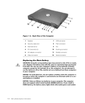
...Hard-disk drive 4 PC Card slots (2) 5 AC adapter connector 6 Video connector 7 USB connector 8 PS/2 connector 9 Fan 10 Docking connector 11 Parallel connector 12 Serial connector Replacing the Main Battery CAUTION: Using the wrong battery type may present a risk of fire or explosion. You can use a battery...computer is installed. If you install a NiMH battery, the battery status lights blink alternately green and amber. 1-10 Dell Latitude System Information Replace the battery only with the same or equivalent type purchased from those computers in your computer. Do not attempt to an...
...Hard-disk drive 4 PC Card slots (2) 5 AC adapter connector 6 Video connector 7 USB connector 8 PS/2 connector 9 Fan 10 Docking connector 11 Parallel connector 12 Serial connector Replacing the Main Battery CAUTION: Using the wrong battery type may present a risk of fire or explosion. You can use a battery...computer is installed. If you install a NiMH battery, the battery status lights blink alternately green and amber. 1-10 Dell Latitude System Information Replace the battery only with the same or equivalent type purchased from those computers in your computer. Do not attempt to an...


