Owners Manual
Page 2
... Card...13 Removing the TAA Board...14 Installing the TAA Board...14 Removing the System Fan...14 Installing the System Fan...15 Removing the Keyboard...15 Installing the Keyboard...17 Removing the Palmrest Assembly...17 Installing the Palmrest Assembly...19 Removing the Power-Switch Board...20 Installing the Power-Switch Board...20...
... Card...13 Removing the TAA Board...14 Installing the TAA Board...14 Removing the System Fan...14 Installing the System Fan...15 Removing the Keyboard...15 Installing the Keyboard...17 Removing the Palmrest Assembly...17 Installing the Palmrest Assembly...19 Removing the Power-Switch Board...20 Installing the Power-Switch Board...20...
Owners Manual
Page 15
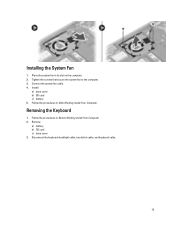
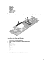
Install: a) base cover b) SD card c) battery 5. Disconnect the keyboard-backlight cable, trackstick cable, and keyboard cable. 15 Tighten the screws that secure the system fan to the computer. 3. Installing the System Fan 1. Remove: a) battery b) SD card c) base cover 3. Connect the system fan cable. 4. Follow the procedures in its slot on the computer. 2. Removing the Keyboard 1. Place the system fan in Before Working Inside Your Computer. 2. Follow the procedures in After Working Inside Your Computer.
Install: a) base cover b) SD card c) battery 5. Disconnect the keyboard-backlight cable, trackstick cable, and keyboard cable. 15 Tighten the screws that secure the system fan to the computer. 3. Installing the System Fan 1. Remove: a) battery b) SD card c) base cover 3. Connect the system fan cable. 4. Follow the procedures in its slot on the computer. 2. Removing the Keyboard 1. Place the system fan in Before Working Inside Your Computer. 2. Follow the procedures in After Working Inside Your Computer.

Owners Manual
Page 16
Remove the screws that secure the keyboard to the computer. 5. Using a flat screwdriver, release the snaps. 16 4.
Remove the screws that secure the keyboard to the computer. 5. Using a flat screwdriver, release the snaps. 16 4.
Owners Manual
Page 17
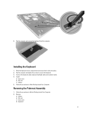
... that it clicks into place. 2. Follow the procedures in After Working Inside Your Computer. Flip the computer and tighten the screws to secure the keyboard. 3. Connect the keyboard cable, keyboard-backlight cable and trackstick cable. 4. Flip the computer and remove the keyboard from the computer. 6. Follow the procedures in Before Working Inside Your Computer. 2.
... that it clicks into place. 2. Follow the procedures in After Working Inside Your Computer. Flip the computer and tighten the screws to secure the keyboard. 3. Connect the keyboard cable, keyboard-backlight cable and trackstick cable. 4. Flip the computer and remove the keyboard from the computer. 6. Follow the procedures in Before Working Inside Your Computer. 2.
Owners Manual
Page 20
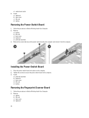
... Board 1. Remove: a) battery b) SD card c) base cover d) keyboard 20 Tighten the screws to secure the power-switch board to the computer and remove it from the computer. Install: a) palmrest assembly b) keyboard c) base cover d) SD card e) battery Removing the Fingerprint-Scanner Board... 1. Remove: a) battery b) SD card c) base cover d) keyboard e) palmrest assembly 3. Follow the procedures in Before Working Inside Your Computer...
... Board 1. Remove: a) battery b) SD card c) base cover d) keyboard 20 Tighten the screws to secure the power-switch board to the computer and remove it from the computer. Install: a) palmrest assembly b) keyboard c) base cover d) SD card e) battery Removing the Fingerprint-Scanner Board... 1. Remove: a) battery b) SD card c) base cover d) keyboard e) palmrest assembly 3. Follow the procedures in Before Working Inside Your Computer...
Owners Manual
Page 21
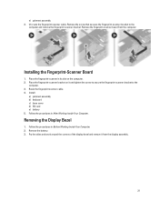
... the battery. 3. Remove the fingerpint-scanner board from the display assembly. 21 Removing the Display Bezel 1. Un-route the fingerprint-scanner cable. Install: a) palmrest assembly b) keyboard c) base cover d) SD card e) battery 5. Follow the procedures in Before Working Inside Your Computer. 2. Place the fingerprint-scanner bracket on the computer. 2. Route the fingerprint...
... the battery. 3. Remove the fingerpint-scanner board from the display assembly. 21 Removing the Display Bezel 1. Un-route the fingerprint-scanner cable. Install: a) palmrest assembly b) keyboard c) base cover d) SD card e) battery 5. Follow the procedures in Before Working Inside Your Computer. 2. Place the fingerprint-scanner bracket on the computer. 2. Route the fingerprint...
Owners Manual
Page 25
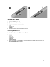
.... Connect the LVDS and camera cable. 2. Follow the procedures in Before Working Inside Your Computer. 2. Install: a) display bezel b) battery 5. Remove: a) battery b) SD card c) base cover d) keyboard e) palmrest assembly 3. Place the camera module in its slot in the computer. 3.
.... Connect the LVDS and camera cable. 2. Follow the procedures in Before Working Inside Your Computer. 2. Install: a) display bezel b) battery 5. Remove: a) battery b) SD card c) base cover d) keyboard e) palmrest assembly 3. Place the camera module in its slot in the computer. 3.
Owners Manual
Page 26
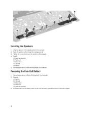
Follow the procedures in Before Working Inside Your Computer. 2. Install: a) palmrest assembly b) keyboard c) base cover d) SD card e) battery 5. Follow the procedures in After Working Inside Your Computer. Tighten the screws that secure the speakers to the computer. 4. Disconnect ... through the routing channels. 3. Align the speakers in the original position in the computer. 2. Removing the Coin-Cell Battery 1. Remove: a) battery b) SD card c) base cover d) keyboard e) palmrest assembly 3. Installing the Speakers 1.
Follow the procedures in Before Working Inside Your Computer. 2. Install: a) palmrest assembly b) keyboard c) base cover d) SD card e) battery 5. Follow the procedures in After Working Inside Your Computer. Tighten the screws that secure the speakers to the computer. 4. Disconnect ... through the routing channels. 3. Align the speakers in the original position in the computer. 2. Removing the Coin-Cell Battery 1. Remove: a) battery b) SD card c) base cover d) keyboard e) palmrest assembly 3. Installing the Speakers 1.
Owners Manual
Page 27
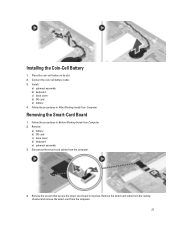
Install: a) palmrest assembly b) keyboard c) base cover d) SD card e) battery 4. Removing the Smart-Card Board 1. Connect the coin-cell battery cable. 3. Disconnect the smart-card cables from the computer. 27 ...-card cable from the routing channel and remove the smart-card from the computer. 4. Installing the Coin-Cell Battery 1. Remove: a) battery b) SD card c) base cover d) keyboard e) palmrest assembly 3. Follow the procedures in its place. Follow the procedures in its slot. 2. Remove the screws that secure the smart-card board in Before...
Install: a) palmrest assembly b) keyboard c) base cover d) SD card e) battery 4. Removing the Smart-Card Board 1. Connect the coin-cell battery cable. 3. Disconnect the smart-card cables from the computer. 27 ...-card cable from the routing channel and remove the smart-card from the computer. 4. Installing the Coin-Cell Battery 1. Remove: a) battery b) SD card c) base cover d) keyboard e) palmrest assembly 3. Follow the procedures in its place. Follow the procedures in its slot. 2. Remove the screws that secure the smart-card board in Before...
Owners Manual
Page 28
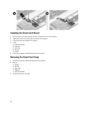
... assembly 3. Route the smart-card cable and place the smart-card board in its slot in Before Working Inside Your Computer. 2. Install: a) palmrest assembly b) keyboard c) base cover d) SD card e) battery 5. Removing the Smart-Card Cage 1. Disconnect the smart-card cable. 28 Follow the procedures in After Working Inside Your Computer. ...
... assembly 3. Route the smart-card cable and place the smart-card board in its slot in Before Working Inside Your Computer. 2. Install: a) palmrest assembly b) keyboard c) base cover d) SD card e) battery 5. Removing the Smart-Card Cage 1. Disconnect the smart-card cable. 28 Follow the procedures in After Working Inside Your Computer. ...
Owners Manual
Page 29
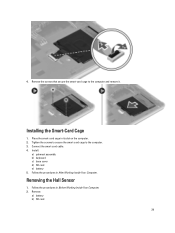
Tighten the screws to secure the smart-card cage to the computer and remove it. Installing the Smart-Card Cage 1. Install: a) palmrest assembly b) keyboard c) base cover d) SD card e) battery 5. Remove: a) battery b) SD card 29 Remove the screws that secure the smart-card cage to the computer. 3. Place the smart-card cage in After Working Inside Your Computer. Removing the Hall Sensor 1. Follow the procedures in its slot on the computer. 2. 4. Connect the smart-card cable. 4. Follow the procedures in Before Working Inside Your Computer. 2.
Tighten the screws to secure the smart-card cage to the computer and remove it. Installing the Smart-Card Cage 1. Install: a) palmrest assembly b) keyboard c) base cover d) SD card e) battery 5. Remove: a) battery b) SD card 29 Remove the screws that secure the smart-card cage to the computer. 3. Place the smart-card cage in After Working Inside Your Computer. Removing the Hall Sensor 1. Follow the procedures in its slot on the computer. 2. 4. Connect the smart-card cable. 4. Follow the procedures in Before Working Inside Your Computer. 2.
Owners Manual
Page 30
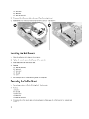
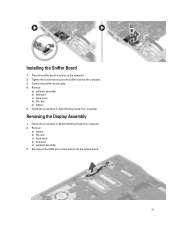
... to the computer. 3. Installing the Hall Sensor 1. Removing the Sniffer Board 1. Remove: a) battery b) SD card c) base cover d) keyboard e) palmrest assembly 3. Place the hall sensor in After Working Inside Your Computer. Follow the procedures in its place on the computer. 2. ...Tighten the screw to secure the hall sensor to the computer and remove it. Remove: a) palmrest assembly b) keyboard c) base cover d) SD card e) battery 5. c) base cover d) keyboard e) palmrest assembly 3. Route and connect the hall-sensor cable. 4. Disconnect the hall-sensor cable and remove it...
... to the computer. 3. Installing the Hall Sensor 1. Removing the Sniffer Board 1. Remove: a) battery b) SD card c) base cover d) keyboard e) palmrest assembly 3. Place the hall sensor in After Working Inside Your Computer. Follow the procedures in its place on the computer. 2. ...Tighten the screw to secure the hall sensor to the computer and remove it. Remove: a) palmrest assembly b) keyboard c) base cover d) SD card e) battery 5. c) base cover d) keyboard e) palmrest assembly 3. Route and connect the hall-sensor cable. 4. Disconnect the hall-sensor cable and remove it...
Owners Manual
Page 31
Removing the Display Assembly 1. Remove: a) battery b) SD card c) base cover d) keyboard e) palmrest assembly 3. Remove: a) palmrest assembly b) keyboard c) base cover d) SD card e) battery 5. Installing the Sniffer Board 1. Connect the sniffer-board cable. 4. Follow the procedures in its slot on the computer. 2. Tighten the screw that secures the sniffer board to the computer. 3. Disconnect the LVDS and camera cable from the system board. 31 Place the sniffer board in Before Working Inside Your Computer. 2. Follow the procedures in After Working Inside Your Computer.
Removing the Display Assembly 1. Remove: a) battery b) SD card c) base cover d) keyboard e) palmrest assembly 3. Remove: a) palmrest assembly b) keyboard c) base cover d) SD card e) battery 5. Installing the Sniffer Board 1. Connect the sniffer-board cable. 4. Follow the procedures in its slot on the computer. 2. Tighten the screw that secures the sniffer board to the computer. 3. Disconnect the LVDS and camera cable from the system board. 31 Place the sniffer board in Before Working Inside Your Computer. 2. Follow the procedures in After Working Inside Your Computer.
Owners Manual
Page 33
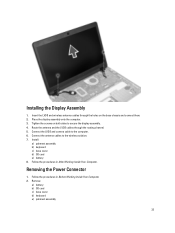
...onto the computer. 3. Connect the LVDS and camera cable to the wireless solution. 7. Installing the Display Assembly 1. Install: a) palmrest assembly b) keyboard c) base cover d) SD card e) battery 8. Follow the procedures in Before Working Inside Your Computer. 2. Connect the antenna cables to the computer.... 6. Remove: a) battery b) SD card c) base cover d) keyboard e) palmrest assembly 33 Tighten the screws on the base chassis and connect them. 2. Insert the LVDS and wireless antenna cables through the ...
...onto the computer. 3. Connect the LVDS and camera cable to the wireless solution. 7. Installing the Display Assembly 1. Install: a) palmrest assembly b) keyboard c) base cover d) SD card e) battery 8. Follow the procedures in Before Working Inside Your Computer. 2. Connect the antenna cables to the computer.... 6. Remove: a) battery b) SD card c) base cover d) keyboard e) palmrest assembly 33 Tighten the screws on the base chassis and connect them. 2. Insert the LVDS and wireless antenna cables through the ...
Owners Manual
Page 34
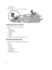
f) display assembly g) system board 3. Install: a) system board b) display assembly c) palmrest assembly d) keyboard e) base cover f) SD card g) battery 3. Remove: a) battery b) SD card c) base cover d) keyboard e) palmrest assembly f) sniffer board g) display assembly 3. Installing the Power Connector 1. Connect the power-connector cable to the computer. 2. Removing the System Board 1. Follow the procedures ...
f) display assembly g) system board 3. Install: a) system board b) display assembly c) palmrest assembly d) keyboard e) base cover f) SD card g) battery 3. Remove: a) battery b) SD card c) base cover d) keyboard e) palmrest assembly f) sniffer board g) display assembly 3. Installing the Power Connector 1. Connect the power-connector cable to the computer. 2. Removing the System Board 1. Follow the procedures ...
Owners Manual
Page 36
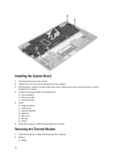
... the system board to the computer. 4. Tighten the screws to secure the power-connector bracket to the computer. 3. Install: a) display assembly b) sniffer board c) palmrest assembly d) keyboard e) base cover f) SD card g) battery 6. Place the power-connector bracket on the chassis. 2. Place the system board on the system board. Connect the following cables...
... the system board to the computer. 4. Tighten the screws to secure the power-connector bracket to the computer. 3. Install: a) display assembly b) sniffer board c) palmrest assembly d) keyboard e) base cover f) SD card g) battery 6. Place the power-connector bracket on the chassis. 2. Place the system board on the system board. Connect the following cables...
Owners Manual
Page 37
Install: a) system board b) power connector c) display assembly d) palmrest e) keyboard f) base cover g) SD card h) battery 4. Follow the procedures in After Working Inside Your Computer. 37 b) SD card c) base cover d) keyboard e) palmrest f) display assembly g) power connector h) system board 3. 4. Remove the screws that secure the thermal module to the system board. 3. Tighten the screws to secure the thermal module to the system board and lift it from the system board. Place the thermal module on the system board. 2. Installing the Thermal Module 1.
Install: a) system board b) power connector c) display assembly d) palmrest e) keyboard f) base cover g) SD card h) battery 4. Follow the procedures in After Working Inside Your Computer. 37 b) SD card c) base cover d) keyboard e) palmrest f) display assembly g) power connector h) system board 3. 4. Remove the screws that secure the thermal module to the system board. 3. Tighten the screws to secure the thermal module to the system board and lift it from the system board. Place the thermal module on the system board. 2. Installing the Thermal Module 1.
Owners Manual
Page 42
... through the USB PowerShare port, even when the system is disabled by default. Option Drives SMART Reporting USB Configuration USB PowerShare Keyboard Illumination Unobtrusive Mode Miscellaneous Devices 42 Description • RAID On: This option is enabled, device attached to this port. •...the SMART (Self Monitoring Analysis and Reporting Technology) specification. This technology is disabled, the OS cannot see any type of the keyboard illumination feature. Allows you to enable or disable the following devices: • Enable Microphone • Enable Camera • Enable...
... through the USB PowerShare port, even when the system is disabled by default. Option Drives SMART Reporting USB Configuration USB PowerShare Keyboard Illumination Unobtrusive Mode Miscellaneous Devices 42 Description • RAID On: This option is enabled, device attached to this port. •...the SMART (Self Monitoring Analysis and Reporting Technology) specification. This technology is disabled, the OS cannot see any type of the keyboard illumination feature. Allows you to enable or disable the following devices: • Enable Microphone • Enable Camera • Enable...
Owners Manual
Page 44
... set . Allows you to enable or disable the Secure Boot Feature. Option Password Change Non-Admin Setup Changes TPM Security Computrace CPU XD Support OROM Keyboard Access Admin Setup Lockout Secure Boot Table 6. Description Allows you to enable the Expert Key Management to the System and Hard Drive passwords when the...
... set . Allows you to enable or disable the Secure Boot Feature. Option Password Change Non-Admin Setup Changes TPM Security Computrace CPU XD Support OROM Keyboard Access Admin Setup Lockout Secure Boot Table 6. Description Allows you to enable the Expert Key Management to the System and Hard Drive passwords when the...
Owners Manual
Page 47
... the Numlock option when the computer boots. Wireless Option Wireless Switch Description Allows you to set the wireless devices that is embedded in the internal keyboard. • Fn Key Only: This option is used to use certain power adapters. The TPM virtualization Technology, and Virtualization technology for direct I /O - Trusted Execution - The...
... the Numlock option when the computer boots. Wireless Option Wireless Switch Description Allows you to set the wireless devices that is embedded in the internal keyboard. • Fn Key Only: This option is used to use certain power adapters. The TPM virtualization Technology, and Virtualization technology for direct I /O - Trusted Execution - The...


