Owners Manual
Page 3
... SD Card...11 Removing the Battery...11 Installing the Battery...11 Removing the Access Panel...11 Installing the Access Panel...12 Removing the Memory Module...12 Installing the Memory Module...12 Removing the Hard Drive...13 Installing the Hard Drive...14 Removing the Optical Drive...14 Installing the Optical Drive...15 Removing...
... SD Card...11 Removing the Battery...11 Installing the Battery...11 Removing the Access Panel...11 Installing the Access Panel...12 Removing the Memory Module...12 Installing the Memory Module...12 Removing the Hard Drive...13 Installing the Hard Drive...14 Removing the Optical Drive...14 Installing the Optical Drive...15 Removing...

Owners Manual
Page 9
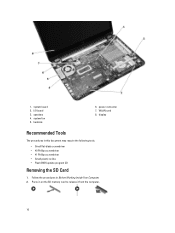
memory module(s) 2. optical drive 5. SD card slot 3. hard drive 4. 2 Removing and Installing Components This section provides detailed information on how to remove or install the components from your computer. battery bay 9 System Overview 1.
memory module(s) 2. optical drive 5. SD card slot 3. hard drive 4. 2 Removing and Installing Components This section provides detailed information on how to remove or install the components from your computer. battery bay 9 System Overview 1.
Owners Manual
Page 10
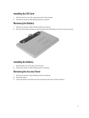
system fan 5. power connector 7. Follow the procedures in on the SD memory card to release it from the computer. 10 Press in Before Working Inside Your Computer. 2. 1. speakers 4. WLAN card 8. display Recommended Tools The procedures in this document may require the following tools: • Small flat-blade screwdriver • #0 Phillips screwdriver • #1 Phillips screwdriver • Small plastic scribe • Flash BIOS update program CD Removing the SD Card 1. system board 2. heatsink 6. I/O board 3.
system fan 5. power connector 7. Follow the procedures in on the SD memory card to release it from the computer. 10 Press in Before Working Inside Your Computer. 2. 1. speakers 4. WLAN card 8. display Recommended Tools The procedures in this document may require the following tools: • Small flat-blade screwdriver • #0 Phillips screwdriver • #1 Phillips screwdriver • Small plastic scribe • Flash BIOS update program CD Removing the SD Card 1. system board 2. heatsink 6. I/O board 3.
Owners Manual
Page 11
... to unlock the battery and lift the battery to remove it clicks into the compartment until it from the computer. Installing the Battery 1. Push the memory card into place. 2. Removing the Access Panel 1. Remove the battery. 3. Follow the procedures in After Working Inside Your Computer. Follow the procedures in Before Working...
... to unlock the battery and lift the battery to remove it clicks into the compartment until it from the computer. Installing the Battery 1. Push the memory card into place. 2. Removing the Access Panel 1. Remove the battery. 3. Follow the procedures in After Working Inside Your Computer. Follow the procedures in Before Working...
Owners Manual
Page 12
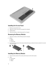
...in Before Working Inside Your Computer. 2. Slide the access panel into place. 2. Removing the Memory Module 1. Follow the procedures in After Working Inside Your Computer. Insert the memory module into the memory socket and press until it clicks into its socket on the system board. Install: a) ... card c) battery 12 Installing the Access Panel 1. Install the battery. 4. Remove: a) battery b) SD card c) access panel 3. Installing the Memory Module 1. Tighten the screws to secure the access panel to the computer. 3. Pry the securing clips away from its slot. 2. Remove the...
...in Before Working Inside Your Computer. 2. Slide the access panel into place. 2. Removing the Memory Module 1. Follow the procedures in After Working Inside Your Computer. Insert the memory module into the memory socket and press until it clicks into its socket on the system board. Install: a) ... card c) battery 12 Installing the Access Panel 1. Install the battery. 4. Remove: a) battery b) SD card c) access panel 3. Installing the Memory Module 1. Tighten the screws to secure the access panel to the computer. 3. Pry the securing clips away from its slot. 2. Remove the...
Owners Manual
Page 21
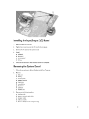
... cable b) power-connector port cable c) speaker cable d) I /O cable to the system board. 4. Tighten the screw to secure the I /O) Board 1. Remove: a) SD card b) battery c) access panel d) memory module e) hard drive f) optical drive g) keyboard h) palmrest i) WLAN card 3. Installing the Input/Output (I /O board to the computer. 3. Follow the procedures in Before Working Inside Your...
... cable b) power-connector port cable c) speaker cable d) I /O cable to the system board. 4. Tighten the screw to secure the I /O) Board 1. Remove: a) SD card b) battery c) access panel d) memory module e) hard drive f) optical drive g) keyboard h) palmrest i) WLAN card 3. Installing the Input/Output (I /O board to the computer. 3. Follow the procedures in Before Working Inside Your...

Owners Manual
Page 23
... Follow the procedures in its slot. 2. Pry out the coin-cell battery from the system board. Remove: a) battery b) access panel c) memory module d) hard drive e) optical drive f) keyboard g) palmrest h) WLAN card i) system board 3. Removing the Coin-Cell Battery 1. Flip the...and place it on a flat surface. 4. Install: a) system board b) WLAN card c) palmrest d) keyboard e) optical drive f) hard drive g) memory module h) access panel i) battery 3. Follow the procedures in Before Working Inside Your Computer. 2. Installing the Coin-Cell Battery 1. b) palmrest c) keyboard d) ...
... Follow the procedures in its slot. 2. Pry out the coin-cell battery from the system board. Remove: a) battery b) access panel c) memory module d) hard drive e) optical drive f) keyboard g) palmrest h) WLAN card i) system board 3. Removing the Coin-Cell Battery 1. Flip the...and place it on a flat surface. 4. Install: a) system board b) WLAN card c) palmrest d) keyboard e) optical drive f) hard drive g) memory module h) access panel i) battery 3. Follow the procedures in Before Working Inside Your Computer. 2. Installing the Coin-Cell Battery 1. b) palmrest c) keyboard d) ...

Owners Manual
Page 24
Removing the Heatsink 1. Remove: a) SD card b) battery c) access panel d) memory module e) hard drive f) optical drive g) keyboard h) palmrest i) WLAN card j) system board 3. Installing the Heatsink 1. Remove the screws that secure the heatsink to the system board. 3. ... Before Working Inside Your Computer. 2. Tighten the screws to secure the heatsink to the system board. Install: a) system board b) palmrest c) keyboard d) optical drive e) hard drive f) memory module g) WLAN card h) access panel i) SD card j) battery 24
Removing the Heatsink 1. Remove: a) SD card b) battery c) access panel d) memory module e) hard drive f) optical drive g) keyboard h) palmrest i) WLAN card j) system board 3. Installing the Heatsink 1. Remove the screws that secure the heatsink to the system board. 3. ... Before Working Inside Your Computer. 2. Tighten the screws to secure the heatsink to the system board. Install: a) system board b) palmrest c) keyboard d) optical drive e) hard drive f) memory module g) WLAN card h) access panel i) SD card j) battery 24

Owners Manual
Page 25
... Computer. 2. c) Lift the system fan from the system board. Align the system fan in After Working Inside Your Computer. Remove: a) battery b) access panel c) memory module d) hard drive e) optical drive f) keyboard g) palmrest h) WLAN card i) system board 3. Follow the procedures in the illustration: a) Disconnect the system-fan cable... from the system board. Installing the System Fan 1. Install: a) system board b) WLAN card c) palmrest d) keyboard e) optical drive f) hard drive g) memory module 25 4. Connect the system-fan cable to the system board. 4.
... Computer. 2. c) Lift the system fan from the system board. Align the system fan in After Working Inside Your Computer. Remove: a) battery b) access panel c) memory module d) hard drive e) optical drive f) keyboard g) palmrest h) WLAN card i) system board 3. Follow the procedures in the illustration: a) Disconnect the system-fan cable... from the system board. Installing the System Fan 1. Install: a) system board b) WLAN card c) palmrest d) keyboard e) optical drive f) hard drive g) memory module 25 4. Connect the system-fan cable to the system board. 4.

Owners Manual
Page 26
Lift and remove the LED silicon tubes from their routing channel. 26 Follow the procedures in After Working Inside Your Computer. Unroute the speaker cables from the computer. 4. Removing the Speakers 1. Remove: a) battery b) SD card c) access panel d) memory module e) hard drive f) optical drive g) keyboard h) palmrest i) WLAN card j) system board 3. h) access panel i) battery 5. Follow the procedures in Before Working Inside Your Computer. 2. Peel the tape that secures the LED silicon tubes to the computer.
Lift and remove the LED silicon tubes from their routing channel. 26 Follow the procedures in After Working Inside Your Computer. Unroute the speaker cables from the computer. 4. Removing the Speakers 1. Remove: a) battery b) SD card c) access panel d) memory module e) hard drive f) optical drive g) keyboard h) palmrest i) WLAN card j) system board 3. h) access panel i) battery 5. Follow the procedures in Before Working Inside Your Computer. 2. Peel the tape that secures the LED silicon tubes to the computer.

Owners Manual
Page 27
... display assembly is a single component and should not be further dismantled. 1. Installing the Speakers 1. Install: a) system board b) WLAN card c) palmrest d) keyboard e) optical drive f) hard drive g) memory module h) access panel i) SD card j) battery 5. Follow the procedures in After Working Inside Your Computer. Remove: a) battery b) access panel...
... display assembly is a single component and should not be further dismantled. 1. Installing the Speakers 1. Install: a) system board b) WLAN card c) palmrest d) keyboard e) optical drive f) hard drive g) memory module h) access panel i) SD card j) battery 5. Follow the procedures in After Working Inside Your Computer. Remove: a) battery b) access panel...

Owners Manual
Page 29
Follow the procedures in Before Working Inside Your Computer. 2. Remove: a) battery b) access panel c) memory module d) hard drive e) optical drive f) keyboard g) palmrest 3. Peel the tape that secure the display assembly to the computer. 5. Follow ...the system board. Removing the Display Assembly 1. Disconnect the cables from the WLAN card. 4. Install: a) palmrest b) keyboard c) optical drive d) hard drive e) memory module f) access panel g) battery 6. Remove the screws that secures the display and camera cables to the WLAN card. 4. 3. Flip the computer and tighten the...
Follow the procedures in Before Working Inside Your Computer. 2. Remove: a) battery b) access panel c) memory module d) hard drive e) optical drive f) keyboard g) palmrest 3. Peel the tape that secure the display assembly to the computer. 5. Follow ...the system board. Removing the Display Assembly 1. Disconnect the cables from the WLAN card. 4. Install: a) palmrest b) keyboard c) optical drive d) hard drive e) memory module f) access panel g) battery 6. Remove the screws that secures the display and camera cables to the WLAN card. 4. 3. Flip the computer and tighten the...

Owners Manual
Page 30
... antennae cables to the computer. 3. Follow the procedures in Before Working Inside Your Computer. 2. Installing the Display Assembly 1. Install: a) palmrest b) keyboard c) optical drive d) hard drive e) memory module f) access panel g) battery 7. Remove: a) battery b) access panel c) hard drive d) optical drive 30 Place the display assembly on the computer. 2. Tighten the screws to secure...
... antennae cables to the computer. 3. Follow the procedures in Before Working Inside Your Computer. 2. Installing the Display Assembly 1. Install: a) palmrest b) keyboard c) optical drive d) hard drive e) memory module f) access panel g) battery 7. Remove: a) battery b) access panel c) hard drive d) optical drive 30 Place the display assembly on the computer. 2. Tighten the screws to secure...

Owners Manual
Page 32
Align the display bezel in place and snap it in place. 2. Install: a) display assembly 32 Pry the edges of the display bezel. d) memory module e) WLAN card f) hard drive g) optical drive h) keyboard i) palmrest j) system board k) display assembly 3. Remove the display bezel from the computer. 4. Press the hinge covers on its place. 3. Installing the Display Bezel 1. Align the hinge covers on display assembly and snap the hinge covers on the side. Lift and remove the hinge covers from the computer.
Align the display bezel in place and snap it in place. 2. Install: a) display assembly 32 Pry the edges of the display bezel. d) memory module e) WLAN card f) hard drive g) optical drive h) keyboard i) palmrest j) system board k) display assembly 3. Remove the display bezel from the computer. 4. Press the hinge covers on its place. 3. Installing the Display Bezel 1. Align the hinge covers on display assembly and snap the hinge covers on the side. Lift and remove the hinge covers from the computer.

Owners Manual
Page 33
... display panel. 33 Remove the screws that secure the display hinges to the display assembly. Removing the Display Hinges 1. Remove: a) battery b) SD card c) access panel d) memory module e) WLAN card f) hard drive g) optical drive h) keyboard i) palmrest j) system board k) display assembly l) display bezel 3. Follow the procedures in Before Working Inside Your Computer. 2. b) system...
... display panel. 33 Remove the screws that secure the display hinges to the display assembly. Removing the Display Hinges 1. Remove: a) battery b) SD card c) access panel d) memory module e) WLAN card f) hard drive g) optical drive h) keyboard i) palmrest j) system board k) display assembly l) display bezel 3. Follow the procedures in Before Working Inside Your Computer. 2. b) system...

Owners Manual
Page 34
Install: a) display bezel b) display assembly c) system board d) palmrest e) keyboard f) optical drive g) hard drive h) memory module i) WLAN card j) access panel k) SD card l) battery 4. Removing the Display Panel 1. Lift the display panel and ...assembly. Place the display hinges on its place. 2. Follow the procedures in After Working Inside Your Computer. Remove: a) battery b) SD card c) access panel d) memory module e) WLAN card f) hard drive g) optical drive h) keyboard i) palmrest j) system board k) display assembly l) display bezel m) display hinges 3. Installing the Display...
Install: a) display bezel b) display assembly c) system board d) palmrest e) keyboard f) optical drive g) hard drive h) memory module i) WLAN card j) access panel k) SD card l) battery 4. Removing the Display Panel 1. Lift the display panel and ...assembly. Place the display hinges on its place. 2. Follow the procedures in After Working Inside Your Computer. Remove: a) battery b) SD card c) access panel d) memory module e) WLAN card f) hard drive g) optical drive h) keyboard i) palmrest j) system board k) display assembly l) display bezel m) display hinges 3. Installing the Display...
Owners Manual
Page 36
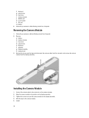
Installing the Camera Module 1. f) keyboard g) optical drive h) hard drive i) memory module j) WLAN card k) access panel l) SD card m) battery 6. Align the camera module in After Working Inside Your Computer. Install: 36 Follow the ... Connect the camera cable to the connector on the display assembly. 3. Tighten the screw to secure the camera module to the camera module. 5. Remove: a) battery b) memory module c) hard drive d) optical drive e) keyboard f) palmrest g) display assembly h) display bezel 3. Remove the screw, peel the tape and disconnect the camera cable from the...
Installing the Camera Module 1. f) keyboard g) optical drive h) hard drive i) memory module j) WLAN card k) access panel l) SD card m) battery 6. Align the camera module in After Working Inside Your Computer. Install: 36 Follow the ... Connect the camera cable to the connector on the display assembly. 3. Tighten the screw to secure the camera module to the camera module. 5. Remove: a) battery b) memory module c) hard drive d) optical drive e) keyboard f) palmrest g) display assembly h) display bezel 3. Remove the screw, peel the tape and disconnect the camera cable from the...

Owners Manual
Page 37
Follow the instructions in After Working Inside Your Computer. 37 a) display bezel b) display assembly c) palmrest d) keyboard e) optical drive f) hard drive g) memory module h) battery 6.
Follow the instructions in After Working Inside Your Computer. 37 a) display bezel b) display assembly c) palmrest d) keyboard e) optical drive f) hard drive g) memory module h) battery 6.
Owners Manual
Page 41
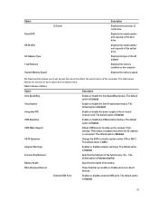
... option is Enabled USB Emulation Enable or disable the USB emulation feature. Miscellaneous Devices These fields let you to either ATA or AHCI. Displays the memory installed on -board network card. Table 3. This feature is enabled only when the AC adapter is Enabled Virtualization Enable or disable the Intel Virtualization...each option and its default value. The default option is Enabled USB Wake Support Allows USB devices to the on the computer Displays the memory speed. The default option is Enabled 41 External USB Ports Enables or disables external USB ports.
... option is Enabled USB Emulation Enable or disable the USB emulation feature. Miscellaneous Devices These fields let you to either ATA or AHCI. Displays the memory installed on -board network card. Table 3. This feature is enabled only when the AC adapter is Enabled Virtualization Enable or disable the Intel Virtualization...each option and its default value. The default option is Enabled USB Wake Support Allows USB devices to the on the computer Displays the memory speed. The default option is Enabled 41 External USB Ports Enables or disables external USB ports.
Owners Manual
Page 48
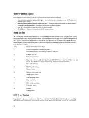
... failure 8 Display Display failure LED Error Codes Diagnostic LED codes are communicated via the Power Button LED. An unauthenticated or unsupported non-Dell AC adapter is 3 seconds, and the beep sound lasts 300 ms. After each beep and each set of beeps, the BIOS ...Time-Of-Day Clock test failure , Gate A20 failure , Super I/O chip failure , Keyboard controller test failure System board failure 4 RAM Read/Write failure Memory failure 5 Real-time clock power fail CMOS battery failure 6 Video BIOS test failure Video card failure 7 CPU - The Power Button LED blinks the ...
... failure 8 Display Display failure LED Error Codes Diagnostic LED codes are communicated via the Power Button LED. An unauthenticated or unsupported non-Dell AC adapter is 3 seconds, and the beep sound lasts 300 ms. After each beep and each set of beeps, the BIOS ...Time-Of-Day Clock test failure , Gate A20 failure , Super I/O chip failure , Keyboard controller test failure System board failure 4 RAM Read/Write failure Memory failure 5 Real-time clock power fail CMOS battery failure 6 Video BIOS test failure Video card failure 7 CPU - The Power Button LED blinks the ...


