Service Manual
Page 3
... Secure Digital Card...15 Base cover...17 Battery...22 Hard drive...26 IO board...29 Touchpad...32 Memory modules...36 SIM Card...37 WLAN card...39 WWAN card...41 WWAN daughterboard...43 Solid-state drive/Intel Optane memory module...47 Speakers...57 System fan...61 Heat sink...65 VGA daughterboard...69 Power-button board...72 System board...75 Display assembly...81 Display bezel...89 Display panel...93 Display cable...99 Power-adapter port...103 Camera...105 Contents 3 Windows 10...5 Before working inside...
... Secure Digital Card...15 Base cover...17 Battery...22 Hard drive...26 IO board...29 Touchpad...32 Memory modules...36 SIM Card...37 WLAN card...39 WWAN card...41 WWAN daughterboard...43 Solid-state drive/Intel Optane memory module...47 Speakers...57 System fan...61 Heat sink...65 VGA daughterboard...69 Power-button board...72 System board...75 Display assembly...81 Display bezel...89 Display panel...93 Display cable...99 Power-adapter port...103 Camera...105 Contents 3 Windows 10...5 Before working inside...
Service Manual
Page 5
... the cable. After you turn off your warranty. You should only perform troubleshooting and simple repairs as authorized in this task CAUTION: To avoid losing data, save and close all open files and exit all open programs before opening the computer cover or panels. WARNING: Before working inside the computer, replace all power sources before you finish working inside your computer Safety instructions Prerequisites Use...
... the cable. After you turn off your warranty. You should only perform troubleshooting and simple repairs as authorized in this task CAUTION: To avoid losing data, save and close all open files and exit all open programs before opening the computer cover or panels. WARNING: Before working inside the computer, replace all power sources before you finish working inside your computer Safety instructions Prerequisites Use...
Service Manual
Page 6
... the power button for shut-down instructions. 3. Turn on your computer. 6 Working on your computer, if applicable. 6. Steps 1. Click or tap . 2. Before working on your computer Steps 1. Save and close all open files and exit all attached devices are using a different operating system, see the documentation of your computer. 4. Connect any media card and optical disc from your computer. 3. Remove any external devices, peripherals, or cables you are turned...
... the power button for shut-down instructions. 3. Turn on your computer. 6 Working on your computer, if applicable. 6. Steps 1. Click or tap . 2. Before working on your computer Steps 1. Save and close all open files and exit all attached devices are using a different operating system, see the documentation of your computer. 4. Connect any media card and optical disc from your computer. 3. Remove any external devices, peripherals, or cables you are turned...
Service Manual
Page 8
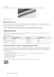
... devices sold, and yet the need for new transfer types • Backward USB 2.0 compatibility • New connectors and cable The topics below cover some of the system or under the keyboard, as in some portable systems. NOTE: The DDR4 memory is imbedded in 1996. Figure 3. If all memory fails, the LCD does not turn on the system display the new ON-FLASH-FLASH or ON-FLASH-ON failure code...
... devices sold, and yet the need for new transfer types • Backward USB 2.0 compatibility • New connectors and cable The topics below cover some of the system or under the keyboard, as in some portable systems. NOTE: The DDR4 memory is imbedded in 1996. Figure 3. If all memory fails, the LCD does not turn on the system display the new ON-FLASH-FLASH or ON-FLASH-ON failure code...
Service Manual
Page 10
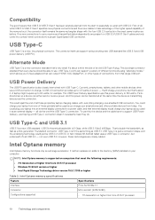
... power - that can output HDMI, VGA, DisplayPort, or other types of those proprietary laptop charging cables, with everything charging via a standard USB connection. This could charge your laptop as a storage accelerator. To use a USB connection to 60 watts, for example. USB Type-C and USB 3.1 USB 3.1 is 5 Gbps, while USB 3.1 Gen2 is10Gbps . It neither replaces nor adds to the memory (RAM) installed on your smartphones and other mobile devices often use this, the device and the cable have adapters...
... power - that can output HDMI, VGA, DisplayPort, or other types of those proprietary laptop charging cables, with everything charging via a standard USB connection. This could charge your laptop as a storage accelerator. To use a USB connection to 60 watts, for example. USB Type-C and USB 3.1 USB 3.1 is 5 Gbps, while USB 3.1 Gen2 is10Gbps . It neither replaces nor adds to the memory (RAM) installed on your smartphones and other mobile devices often use this, the device and the cable have adapters...
Service Manual
Page 26
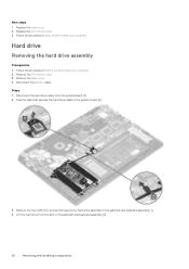
... the tape that secure the hard drive assembly to the system board [2]. 3. Replace the base cover 2. Steps 1. Next steps 1. Remove the SD memory card 3. Disconnect the battery cable. Remove the four (M2x4.5) screws that secures the hard drive cable to the palmrest and keyboard assembly [1]. 4. Replace the SD memory card 3. Lift the hard drive from the system board [1]. 2. Follow the procedure in before working inside your computer Hard drive Removing the hard drive assembly Prerequisites 1. Follow the...
... the tape that secure the hard drive assembly to the system board [2]. 3. Replace the base cover 2. Steps 1. Next steps 1. Remove the SD memory card 3. Disconnect the battery cable. Remove the four (M2x4.5) screws that secures the hard drive cable to the palmrest and keyboard assembly [1]. 4. Replace the SD memory card 3. Lift the hard drive from the system board [1]. 2. Follow the procedure in before working inside your computer Hard drive Removing the hard drive assembly Prerequisites 1. Follow the...
Service Manual
Page 29
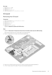
... procedure in after working inside your computer. 2. Peel the I /O board, along with 42 Whr battery Steps 1. NOTE: Required for systems with the cable, off the palm rest and keyboard assembly [2]. Replace the battery cable. 2. Remove the hard drive assembly. Remove the two (M2x3) screws that secure the I /O board also removes the coin-cell battery which resets the CMOS settings. Replace the base cover 3. Remove the SD memory card. 3. NOTE: Removing the I /O board to the palm...
... procedure in after working inside your computer. 2. Peel the I /O board, along with 42 Whr battery Steps 1. NOTE: Required for systems with the cable, off the palm rest and keyboard assembly [2]. Replace the battery cable. 2. Remove the hard drive assembly. Remove the two (M2x3) screws that secure the I /O board also removes the coin-cell battery which resets the CMOS settings. Replace the base cover 3. Remove the SD memory card. 3. NOTE: Removing the I /O board to the palm...
Service Manual
Page 36
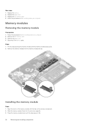
... the battery cable. Remove the memory module from the memory module slot [2]. Installing the memory module Steps 1. Slide the memory module firmly into the slot at an angle [1]. 3. Remove the SD memory card 3. Replace the SD memory card 4. Align the notch on the memory module with the tab on the memory-module slot. 2. Remove the base cover 4. Follow the procedure in after working inside your computer 2. Pry the clips securing the memory module until the clips secure it [2]. 36 Removing and installing...
... the battery cable. Remove the memory module from the memory module slot [2]. Installing the memory module Steps 1. Slide the memory module firmly into the slot at an angle [1]. 3. Remove the SD memory card 3. Replace the SD memory card 4. Align the notch on the memory module with the tab on the memory-module slot. 2. Remove the base cover 4. Follow the procedure in after working inside your computer 2. Pry the clips securing the memory module until the clips secure it [2]. 36 Removing and installing...
Service Manual
Page 111
... FN+PWR buttons while powering on a specific device, press Esc and click Yes to select the Diagnostics option and then press Enter. Always ensure that you are present at the computer terminal when the diagnostic tests are completed successfully • View error messages that inform you if tests are performed. In the boot menu screen, use Up/Down arrow key to stop...
... FN+PWR buttons while powering on a specific device, press Esc and click Yes to select the Diagnostics option and then press Enter. Always ensure that you are present at the computer terminal when the diagnostic tests are completed successfully • View error messages that inform you if tests are performed. In the boot menu screen, use Up/Down arrow key to stop...
Service Manual
Page 113
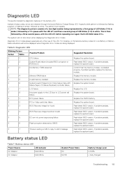
... Memory/ RAM detected 2 4 Memory/RAM failure 2 5 Invalid memory installed 2 6 System board/Chipset Error/Clock failure/Gate A20 failure/Super I/O failure/Keyboard controller failure 2 7 LCD failure 2 8 No power supply to the LCD due to LCD power rail failure 3 1 RTC power failure 3 2 PCI or Video card/chip failure 3 3 BIOS Recovery image not found 3 4 BIOS Recovery image found but invalid 3 5 EC ran into power sequencing failure. 3 6 Flash corruption detected by flashing a pattern of a two-digit number being displayed. Replace the memory module. Replace...
... Memory/ RAM detected 2 4 Memory/RAM failure 2 5 Invalid memory installed 2 6 System board/Chipset Error/Clock failure/Gate A20 failure/Super I/O failure/Keyboard controller failure 2 7 LCD failure 2 8 No power supply to the LCD due to LCD power rail failure 3 1 RTC power failure 3 2 PCI or Video card/chip failure 3 3 BIOS Recovery image not found 3 4 BIOS Recovery image found but invalid 3 5 EC ran into power sequencing failure. 3 6 Flash corruption detected by flashing a pattern of a two-digit number being displayed. Replace the memory module. Replace...
Setup and specifications guide
Page 3
......14 Memory...15 Storage...15 Intel Optane memory-optional...15 System board connectors...16 Media card-reader...16 Audio...16 Video card...16 Camera...17 Communication...17 Wireless...17 Ports and connectors...18 Display...18 Keyboard...18 Touchpad...19 Operating system...19 Battery...19 Power adapter...20 Dimensions and weight...20 Computer environment...21 Security...21 Security Software...21 Miscellaneous software...22 4 Software...23 Downloading drivers...23 5 System setup...24 System setup...24 Boot options...24 System configuration...25 Video screen options...27...
......14 Memory...15 Storage...15 Intel Optane memory-optional...15 System board connectors...16 Media card-reader...16 Audio...16 Video card...16 Camera...17 Communication...17 Wireless...17 Ports and connectors...18 Display...18 Keyboard...18 Touchpad...19 Operating system...19 Battery...19 Power adapter...20 Dimensions and weight...20 Computer environment...21 Security...21 Security Software...21 Miscellaneous software...22 4 Software...23 Downloading drivers...23 5 System setup...24 System setup...24 Boot options...24 System configuration...25 Video screen options...27...
Setup and specifications guide
Page 24
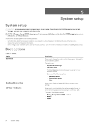
... of hard drive installed, and enabling or disabling base devices. 5 System setup System setup CAUTION: Unless you are : • Windows Boot Manager • UEFI Hard Drive The Boot Sequence window allows you to find an operating system. Use the BIOS Setup program for future reference. Certain changes can make your computer, such as the amount of RAM and the size of the hard drive. • Change the system configuration information. • Set or change a user-selectable option, such as the user password, type...
... of hard drive installed, and enabling or disabling base devices. 5 System setup System setup CAUTION: Unless you are : • Windows Boot Manager • UEFI Hard Drive The Boot Sequence window allows you to find an operating system. Use the BIOS Setup program for future reference. Certain changes can make your computer, such as the amount of RAM and the size of the hard drive. • Change the system configuration information. • Set or change a user-selectable option, such as the user password, type...
Setup and specifications guide
Page 25
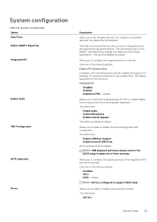
... support RAID mode. The options are: • Enable USB Boot Support • Enable External USB Ports All the options are : • SATA-0 System setup 25 Allows you to configure the operating mode of the integrated SATA hard drive controller. Allows you to enable or disable the internal/integrated USB configuration. The options are set the date and time. Integrated NIC • Disabled • Enabled • Enabled w/PXE-Default Allows you to use enabled NICs. The change to switch all integrated audio On/Off, or enable/disable the microphone...
... support RAID mode. The options are: • Enable USB Boot Support • Enable External USB Ports All the options are : • SATA-0 System setup 25 Allows you to configure the operating mode of the integrated SATA hard drive controller. Allows you to enable or disable the internal/integrated USB configuration. The options are set the date and time. Integrated NIC • Disabled • Enabled • Enabled w/PXE-Default Allows you to use enabled NICs. The change to switch all integrated audio On/Off, or enable/disable the microphone...
Setup and specifications guide
Page 26
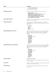
... the backlight is running only on board devices. • Enable Camera-Default • Enable Hard Drive Free Fall Protection-Default • Enable Secure Digital (SD) Card-Default • Secure Digital Card (SD) Read-Only Mode • Secure Digital (SD) Card Boot Allows you to enable or disable the touch screen in the system. Allows you to enable or disable various on battery power. It is set to 'OFF' by default. The Keyboard Backlight timeout value is only in...
... the backlight is running only on board devices. • Enable Camera-Default • Enable Hard Drive Free Fall Protection-Default • Enable Secure Digital (SD) Card-Default • Secure Digital Card (SD) Read-Only Mode • Secure Digital (SD) Card Boot Allows you to enable or disable the touch screen in the system. Allows you to enable or disable various on battery power. It is set to 'OFF' by default. The Keyboard Backlight timeout value is only in...
Setup and specifications guide
Page 27
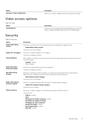
...% default). Option Dell Type-C Dock Configuration Description Allows you to enable or disable CPU XD support. This option is enabled by the admin password. • Allow Wireless Switch Changes This option is set. Allows you to update the system BIOS through UEFI capsule update packages. • Enable UEFI Capsule Firmware Updates This option is not set by default. The options are allowed when an Administrator Password is not set the display brightness depending upon the power source. Security Table 30. If disabled the setup options...
...% default). Option Dell Type-C Dock Configuration Description Allows you to enable or disable CPU XD support. This option is enabled by the admin password. • Allow Wireless Switch Changes This option is set. Allows you to update the system BIOS through UEFI capsule update packages. • Enable UEFI Capsule Firmware Updates This option is not set by default. The options are allowed when an Administrator Password is not set the display brightness depending upon the power source. Security Table 30. If disabled the setup options...
Setup and specifications guide
Page 28
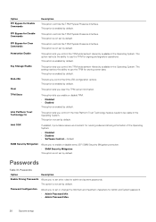
... to set or change the minimum and maximum characters for running codes and storing information of the Operating System. • Disabled • Enabled • Software Control-Default SMM Security Mitigation Allows you control the TPM endorsement Hierarchy available in the Operating System. This option not set by default. This option is enabled by default. Passwords Option Description Enable Strong Passwords Allows you clear the TPM owner information. PPI Bypass for Enable Commands Description This option controls...
... to set or change the minimum and maximum characters for running codes and storing information of the Operating System. • Disabled • Enabled • Software Control-Default SMM Security Mitigation Allows you control the TPM endorsement Hierarchy available in the Operating System. This option not set by default. This option is enabled by default. Passwords Option Description Enable Strong Passwords Allows you clear the TPM owner information. PPI Bypass for Enable Commands Description This option controls...
Setup and specifications guide
Page 29
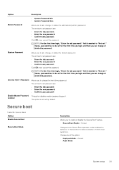
...; Enter the old password: • Enter the new password: • Confirm new password: Click OK once you can change or delete the password. System Password Allows you to enable or disable the Secure Boot Feature. • Secure Boot Enable-Default Changes to the Secure Boot operation mode modifies the behaviour of Secure Boot to set the password. The entries to allow evaluation of the option: • Deployed Mode-Default • Audit Mode System setup 29 Secure Boot Option Enable Secure Boot Secure Boot Mode...
...; Enter the old password: • Enter the new password: • Confirm new password: Click OK once you can change or delete the password. System Password Allows you to enable or disable the Secure Boot Feature. • Secure Boot Enable-Default Changes to the Secure Boot operation mode modifies the behaviour of Secure Boot to set the password. The entries to allow evaluation of the option: • Deployed Mode-Default • Audit Mode System setup 29 Secure Boot Option Enable Secure Boot Secure Boot Mode...
Setup and specifications guide
Page 31
... block entering to sleep in manufacturing mode. Battery Charge Configuration Allows you to enable USB devices to improve the battery health. The options are : • Disabled-Default • Every Day • Weekdays • Select Days This option is not set by default. NOTE: All charging mode may not be enabled in the operating system. Does not allow the system to select the charging mode for all the batteries. Enable USB Wake Support Allows you to power on...
... block entering to sleep in manufacturing mode. Battery Charge Configuration Allows you to enable USB devices to improve the battery health. The options are : • Disabled-Default • Every Day • Weekdays • Select Days This option is not set by default. NOTE: All charging mode may not be enabled in the operating system. Does not allow the system to select the charging mode for all the batteries. Enable USB Wake Support Allows you to power on...
Setup and specifications guide
Page 32
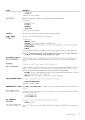
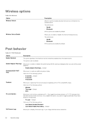
...; Lock Mode Disable/Standard • Lock Mode Enable/Secondary-Default Full Screen Logo Allows you to create an additional preboot delay. Wireless Option Wireless Switch Wireless Device Enable Description Allows to display full screen logo, if your image matches screen resolution. 32 System setup Allows you to set by the wireless switch. POST Behavior Option Enable Numlock Description The option specifies if the Numlock function should be controlled by default. The option is set the wireless devices that can be enabled when the system boots. Wireless options...
...; Lock Mode Disable/Standard • Lock Mode Enable/Secondary-Default Full Screen Logo Allows you to create an additional preboot delay. Wireless Option Wireless Switch Wireless Device Enable Description Allows to display full screen logo, if your image matches screen resolution. 32 System setup Allows you to set by the wireless switch. POST Behavior Option Enable Numlock Description The option specifies if the Numlock function should be controlled by default. The option is set the wireless devices that can be enabled when the system boots. Wireless options...
Setup and specifications guide
Page 33
...; Disabled Virtualization support Table 38. Bios Recovery from Hard Drive BIOS Recovery from the system. System setup 33 Click one of your computer. BIOS Auto-Recovery-Allows you to recover the corrupted BIOS from a recovery file on Warnings and Errors This feature replaces the external NIC MAC address with the selected MAC address from Hard Drive-This option is not set by default. NOTE: BIOS Recovery from utilizing the additional hardware capabilities provided by default. BIOS Auto-Recovery Allows...
...; Disabled Virtualization support Table 38. Bios Recovery from Hard Drive BIOS Recovery from the system. System setup 33 Click one of your computer. BIOS Auto-Recovery-Allows you to recover the corrupted BIOS from a recovery file on Warnings and Errors This feature replaces the external NIC MAC address with the selected MAC address from Hard Drive-This option is not set by default. NOTE: BIOS Recovery from utilizing the additional hardware capabilities provided by default. BIOS Auto-Recovery Allows...


