
Owner's Manual
Page 3
......9 Removing The Battery...9 Installing The Battery...10 Removing The Base Cover...10 Installing The Base Cover...10 Removing The Memory...10 Installing The Memory...11 Removing The Hard Drive...11 Installing The Hard Drive...12 Removing The Display Bezel...12 Installing the Display Bezel...13 Removing The Camera...13 Installing The Camera...13 Removing...
......9 Removing The Battery...9 Installing The Battery...10 Removing The Base Cover...10 Installing The Base Cover...10 Removing The Memory...10 Installing The Memory...11 Removing The Hard Drive...11 Installing The Hard Drive...12 Removing The Display Bezel...12 Installing the Display Bezel...13 Removing The Camera...13 Installing The Camera...13 Removing...
Owner's Manual
Page 12
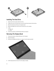
... drive. 3. Follow the procedures in After Working Inside Your Computer. Lift the display bezel and remove it from the display assembly. 12 Installing The Hard Drive 1. Removing The Display Bezel 1. Gently pry the display bezel inside out to release it from the display assembly. 4. Slide the hard drive into the bay on Your Computer. 2. Remove... hard-drive bracket with the hard drive. 2. Tighten the screws on the hard drive to secure the hard-drive bracket to the computer. 5. Install: a) base cover b) battery 6.
... drive. 3. Follow the procedures in After Working Inside Your Computer. Lift the display bezel and remove it from the display assembly. 12 Installing The Hard Drive 1. Removing The Display Bezel 1. Gently pry the display bezel inside out to release it from the display assembly. 4. Slide the hard drive into the bay on Your Computer. 2. Remove... hard-drive bracket with the hard drive. 2. Tighten the screws on the hard drive to secure the hard-drive bracket to the computer. 5. Install: a) base cover b) battery 6.

Owner's Manual
Page 18
... base that secures the WLAN card. 5. Remove the screw that secures the display assembly. 18 Connect the antenna cables to the computer. 3. Install: a) palmrest b) keyboard c) hard drive d) base cover e) battery 5. Remove: a) battery b) base cover c) hard drive d) keyboard e) palmrest 3. Remove: a) battery b) base cover c) hard drive d) keyboard e) palmrest 3. Insert the WLAN card into its connector. 2. Follow...
... base that secures the WLAN card. 5. Remove the screw that secures the display assembly. 18 Connect the antenna cables to the computer. 3. Install: a) palmrest b) keyboard c) hard drive d) base cover e) battery 5. Remove: a) battery b) base cover c) hard drive d) keyboard e) palmrest 3. Remove: a) battery b) base cover c) hard drive d) keyboard e) palmrest 3. Insert the WLAN card into its connector. 2. Follow...
Owner's Manual
Page 22
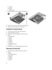
...slot. 3. Connect the power connector cable to the system board. 2. Remove: a) battery b) secure digital (SD) card c) base cover d) keyboard e) hard drive f) memory g) palmrest 22 Installing The System Board 1. Follow the procedures in Before Working on Your Computer. ... the system board from the system board. 4. Install: a) display assembly b) coin-cell c) palmrest d) memory e) hard drive f) keyboard g) base cover h) secure digital (SD) Card i) battery 5. f) hard drive g) palmrest h) coin-cell i) display assembly 3. Follow the procedures in After Working Inside Your Computer...
...slot. 3. Connect the power connector cable to the system board. 2. Remove: a) battery b) secure digital (SD) card c) base cover d) keyboard e) hard drive f) memory g) palmrest 22 Installing The System Board 1. Follow the procedures in Before Working on Your Computer. ... the system board from the system board. 4. Install: a) display assembly b) coin-cell c) palmrest d) memory e) hard drive f) keyboard g) base cover h) secure digital (SD) Card i) battery 5. f) hard drive g) palmrest h) coin-cell i) display assembly 3. Follow the procedures in After Working Inside Your Computer...
Owner's Manual
Page 23
... secure the heat sink in place. 3. Disconnect the heat sink cable from the system board. Remove: a) battery b) secure digital (SD) card c) base cover d) keyboard e) hard drive f) memory g) palmrest h) display assembly i) system board 23 Follow the procedures in After Working Inside Your Computer. Loosen the captive screws that secure the heat sink to...
... secure the heat sink in place. 3. Disconnect the heat sink cable from the system board. Remove: a) battery b) secure digital (SD) card c) base cover d) keyboard e) hard drive f) memory g) palmrest h) display assembly i) system board 23 Follow the procedures in After Working Inside Your Computer. Loosen the captive screws that secure the heat sink to...
Owner's Manual
Page 24
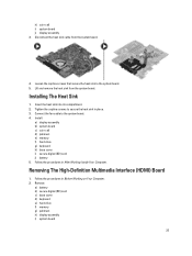
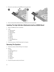
Install: a) display assembly b) system board c) display assembly d) palmrest e) memory f) hard drive g) keyboard h) base cover i) secure digital (SD) card j) battery 3. Disconnect the speaker cable from the system board. 3. Replace the HDMI board into its compartment. 2. Follow... Computer. Remove the High-Definition Multimedia Interface (HDMI) board from the I/O board. 24 Remove: a) battery b) secure digital (SD) card c) base cover d) keyboard e) hard drive f) memory g) palmrest h) system board i) coin-cell 3. Installing The High-Definition Multimedia Interface (HDMI) Board 1.
Install: a) display assembly b) system board c) display assembly d) palmrest e) memory f) hard drive g) keyboard h) base cover i) secure digital (SD) card j) battery 3. Disconnect the speaker cable from the system board. 3. Replace the HDMI board into its compartment. 2. Follow... Computer. Remove the High-Definition Multimedia Interface (HDMI) board from the I/O board. 24 Remove: a) battery b) secure digital (SD) card c) base cover d) keyboard e) hard drive f) memory g) palmrest h) system board i) coin-cell 3. Installing The High-Definition Multimedia Interface (HDMI) Board 1.
Owner's Manual
Page 26
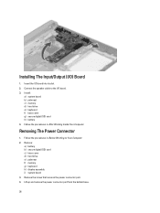
... connector port from the bottom base. 26 Remove the screw that secures the power connector port. 4. Install: a) system board b) palmrest c) memory d) hard drive e) keyboard f) base cover g) secure digital (SD) card h) battery 4. Connect the speaker cable to the I /O) Board 1. Insert the I/O board into its slot. 2. Removing The Power Connector 1. Follow the procedures...
... connector port from the bottom base. 26 Remove the screw that secures the power connector port. 4. Install: a) system board b) palmrest c) memory d) hard drive e) keyboard f) base cover g) secure digital (SD) card h) battery 4. Connect the speaker cable to the I /O) Board 1. Insert the I/O board into its slot. 2. Removing The Power Connector 1. Follow the procedures...
Owner's Manual
Page 27
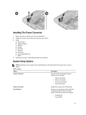
...on your computer. • System Information • Memory Information • Processor Information • Device Information Battery Information Boot Sequence Displays the charge status of your computer and its compartment. 2. Table 1. General Option Description System Information This section lists the primary ...the below options are selected. • Diskette Drive • Internal HDD 27 Install: a) system board b) display assembly c) palmrest d) memory e) hard drive f) keyboard g) base cover h) decure digital (SD) card i) battery 4. Installing The Power Connector 1.
...on your computer. • System Information • Memory Information • Processor Information • Device Information Battery Information Boot Sequence Displays the charge status of your computer and its compartment. 2. Table 1. General Option Description System Information This section lists the primary ...the below options are selected. • Diskette Drive • Internal HDD 27 Install: a) system board b) display assembly c) palmrest d) memory e) hard drive f) keyboard g) base cover h) decure digital (SD) card i) battery 4. Installing The Power Connector 1.


