Owner's Manual (PDF)
Page 5
11 VESA-Mount Bracket 43 Removing the VESA-Mount Bracket 43 Replacing the VESA-Mount Bracket 44 12 Hard Drive 45 Removing the Hard Drive 45 Replacing the Hard Drive 48 13 System-Board Shield 49 Removing the System-Board Shield 49 Replacing the System-Board Shield 51 14 TV Tuner Card 53 Removing the TV Tuner Card 53 Replacing the TV Tuner Card 56 15 Wireless Mini-Card 57 Removing the Wireless Mini-Card 57 Replacing the Wireless Mini-Card 59 Contents 5
11 VESA-Mount Bracket 43 Removing the VESA-Mount Bracket 43 Replacing the VESA-Mount Bracket 44 12 Hard Drive 45 Removing the Hard Drive 45 Replacing the Hard Drive 48 13 System-Board Shield 49 Removing the System-Board Shield 49 Replacing the System-Board Shield 51 14 TV Tuner Card 53 Removing the TV Tuner Card 53 Replacing the TV Tuner Card 56 15 Wireless Mini-Card 57 Removing the Wireless Mini-Card 57 Replacing the Wireless Mini-Card 59 Contents 5
Owner's Manual (PDF)
Page 16
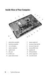
Inside View of Your Computer 4 3 2 1 5 6 7 8 16 15 1 optical-drive assembly 3 hard-drive assembly 5 coin-cell battery 7 memory module(s) 9 system board 11 I/O cover 13 B-CAS card 15 power-button board 11 12 13 14 9 10 2 power-supply unit 4 processor heat-sink fan 6 processor heat-sink 8 wireless Mini-Card 10 speakers (2) 12 I/O board shield 14 power-supply fan 16 converter board 16 Technical Overview
Inside View of Your Computer 4 3 2 1 5 6 7 8 16 15 1 optical-drive assembly 3 hard-drive assembly 5 coin-cell battery 7 memory module(s) 9 system board 11 I/O cover 13 B-CAS card 15 power-button board 11 12 13 14 9 10 2 power-supply unit 4 processor heat-sink fan 6 processor heat-sink 8 wireless Mini-Card 10 speakers (2) 12 I/O board shield 14 power-supply fan 16 converter board 16 Technical Overview
Owner's Manual (PDF)
Page 45
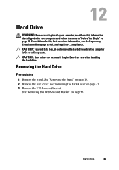
Exercise care when handling the hard drive. See "Removing the Back Cover" on page 43. Hard Drive 45 For additional safety best practices information, see the Regulatory Compliance Homepage at dell.com/regulatory_compliance. Removing the Hard Drive Prerequisites 1 Remove the stand. CAUTION: Hard drives are extremely fragile. See "Removing the VESA-Mount Bracket" on page 23. 3 Remove the VESA-mount...
Exercise care when handling the hard drive. See "Removing the Back Cover" on page 43. Hard Drive 45 For additional safety best practices information, see the Regulatory Compliance Homepage at dell.com/regulatory_compliance. Removing the Hard Drive Prerequisites 1 Remove the stand. CAUTION: Hard drives are extremely fragile. See "Removing the VESA-Mount Bracket" on page 23. 3 Remove the VESA-mount...
Owner's Manual (PDF)
Page 46
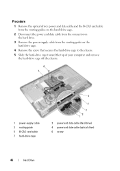
... guide on the hard drive cage. 4 Remove the screw that secures the hard-drive cage to the chassis. 5 Slide the hard-drive cage toward the top of your computer and remove the hard-drive cage off the chassis. 6 7 1 power-supply cable 3 routing guide 5 B-CAS card cable 7 hard-drive cage 5 4 3 2 1 2 power and data cable (hard drive) 4 power and date cable (optical drive) 6 screw 46 Hard Drive
... guide on the hard drive cage. 4 Remove the screw that secures the hard-drive cage to the chassis. 5 Slide the hard-drive cage toward the top of your computer and remove the hard-drive cage off the chassis. 6 7 1 power-supply cable 3 routing guide 5 B-CAS card cable 7 hard-drive cage 5 4 3 2 1 2 power and data cable (hard drive) 4 power and date cable (optical drive) 6 screw 46 Hard Drive

Owner's Manual (PDF)
Page 47
6 Remove the screws that secure the hard-drive cage to the hard drive. 7 Slide the hard drive out of the hard-drive cage. 1 2 3 1 hard drive 3 hard-drive cage 2 screws (4) Hard Drive 47
6 Remove the screws that secure the hard-drive cage to the hard drive. 7 Slide the hard drive out of the hard-drive cage. 1 2 3 1 hard drive 3 hard-drive cage 2 screws (4) Hard Drive 47
Owner's Manual (PDF)
Page 48
...the B-CAS card cable through the routing guides on the hard-drive cage. 7 Route the hard-drive's power and data cable through the routing guide on the hard-drive cage. 8 Connect the power and data cable to the hard drive. 4 Place the hard-drive cage on the chassis and slide it toward the bottom of... your computer. Postrequisites 1 Replace the VESA-mount bracket. See "Replacing the VESA-Mount Bracket" on page 13. 48 Hard Drive Ensure that secure the hard-drive cage to the connector on page 24. 3 Replace the stand. See "Replacing the Stand" on page 21. 4 Follow the instructions...
...the B-CAS card cable through the routing guides on the hard-drive cage. 7 Route the hard-drive's power and data cable through the routing guide on the hard-drive cage. 8 Connect the power and data cable to the hard drive. 4 Place the hard-drive cage on the chassis and slide it toward the bottom of... your computer. Postrequisites 1 Replace the VESA-mount bracket. See "Replacing the VESA-Mount Bracket" on page 13. 48 Hard Drive Ensure that secure the hard-drive cage to the connector on page 24. 3 Replace the stand. See "Replacing the Stand" on page 21. 4 Follow the instructions...
Owner's Manual (PDF)
Page 86
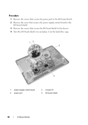
Procedure 1 Remove the screws that secure the power port to the I/O board shield. 2 Remove the screw that secures the power supply control board to the I/O board shield. 3 Remove the screws that secure the I/O board shield to the chassis. 4 Turn the I/O board shield over and place it on the hard-drive cage. 12 3 4 1 power-supply control board 3 power port 2 screws (7) 4 I/O board shield 86 I/O Board Shield
Procedure 1 Remove the screws that secure the power port to the I/O board shield. 2 Remove the screw that secures the power supply control board to the I/O board shield. 3 Remove the screws that secure the I/O board shield to the chassis. 4 Turn the I/O board shield over and place it on the hard-drive cage. 12 3 4 1 power-supply control board 3 power port 2 screws (7) 4 I/O board shield 86 I/O Board Shield
Owner's Manual (PDF)
Page 117
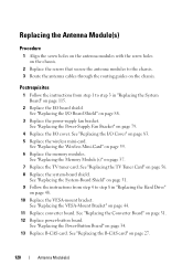
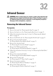
...2 Remove the back cover. See "Removing the VESA-Mount Bracket" on page 43. 8 Follow the instructions from step 1 to step 5 in "Removing the Hard Drive" on page 53. 11 Remove the memory modules. See "Removing the TV Tuner Card" on page 45. 9 Remove the system-board shield. Antenna Module(s) ...WARNING: Before working inside your computer, read the safety information that shipped with your computer and follow the steps in "Removing the Optical Drive" on page 25. 5 Remove the power-button board. For additional safety best practices information, see the Regulatory Compliance Homepage at...
...2 Remove the back cover. See "Removing the VESA-Mount Bracket" on page 43. 8 Follow the instructions from step 1 to step 5 in "Removing the Hard Drive" on page 53. 11 Remove the memory modules. See "Removing the TV Tuner Card" on page 45. 9 Remove the system-board shield. Antenna Module(s) ...WARNING: Before working inside your computer, read the safety information that shipped with your computer and follow the steps in "Removing the Optical Drive" on page 25. 5 Remove the power-button board. For additional safety best practices information, see the Regulatory Compliance Homepage at...
Owner's Manual (PDF)
Page 120
.... 10 Replace the VESA-mount bracket. See "Replacing the System-Board Shield" on page 51. 9 Follow the instructions from step 1 to step 3 in "Replacing the Hard Drive" on page 83. 5 Replace the wireless mini-card. See "Replacing the B-CAS card" on page 37. 7 Replace the TV tuner card. See "Replacing the Memory...
.... 10 Replace the VESA-mount bracket. See "Replacing the System-Board Shield" on page 51. 9 Follow the instructions from step 1 to step 3 in "Replacing the Hard Drive" on page 83. 5 Replace the wireless mini-card. See "Replacing the B-CAS card" on page 37. 7 Replace the TV tuner card. See "Replacing the Memory...
Owner's Manual (PDF)
Page 123
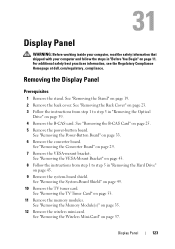
... Panel WARNING: Before working inside your computer, read the safety information that shipped with your computer and follow the steps in "Removing the Hard Drive" on page 45. 9 Remove the system-board shield. Removing the Display Panel Prerequisites 1 Remove the stand. See "Removing the B-CAS... "Before You Begin" on page 39. 4 Remove the B-CAS card. For additional safety best practices information, see the Regulatory Compliance Homepage at dell.com/regulatory_compliance. See "Removing the TV Tuner Card" on page 25. 5 Remove the power-button board. Display Panel 123 See "Removing the ...
... Panel WARNING: Before working inside your computer, read the safety information that shipped with your computer and follow the steps in "Removing the Hard Drive" on page 45. 9 Remove the system-board shield. Removing the Display Panel Prerequisites 1 Remove the stand. See "Removing the B-CAS... "Before You Begin" on page 39. 4 Remove the B-CAS card. For additional safety best practices information, see the Regulatory Compliance Homepage at dell.com/regulatory_compliance. See "Removing the TV Tuner Card" on page 25. 5 Remove the power-button board. Display Panel 123 See "Removing the ...
Owner's Manual (PDF)
Page 129
See "Replacing the System-Board Shield" on page 51. 21 Follow the instructions from step 4 to step 8 in replacing the hard-drive 22 Replace the VESA-mount bracket. See "Replacing the B-CAS card" on page 27. 26 Follow the instructions from step 4 to step 6 in "After Working ...Inside Your Computer" on page 21. 29 Follow the instructions in replacing the optical-drive 27 Replace the back cover. See "Replacing the Stand" on page 13. Display Panel 129 See "Replacing the Converter Board" on page 44. 23 Replace...
See "Replacing the System-Board Shield" on page 51. 21 Follow the instructions from step 4 to step 8 in replacing the hard-drive 22 Replace the VESA-mount bracket. See "Replacing the B-CAS card" on page 27. 26 Follow the instructions from step 4 to step 6 in "After Working ...Inside Your Computer" on page 21. 29 Follow the instructions in replacing the optical-drive 27 Replace the back cover. See "Replacing the Stand" on page 13. Display Panel 129 See "Replacing the Converter Board" on page 44. 23 Replace...
Owner's Manual (PDF)
Page 131
See "Removing the Back Cover" on page 23. 3 Follow the instructions from step 1 to step 3 in "Removing the Hard Drive" on page 45. 9 Remove the system-board shield. See "Removing the B-CAS Card" on page 33. 6 Remove the converter board. See "Removing the Power-...See "Removing the Memory Module(s)" on page 53. 11 Remove the memory modules. For additional safety best practices information, see the Regulatory Compliance Homepage at dell.com/regulatory_compliance. See "Removing the VESA-Mount Bracket" on page 43. 8 Follow the instructions from step 1 to step 5 in "Removing the Optical...
See "Removing the Back Cover" on page 23. 3 Follow the instructions from step 1 to step 3 in "Removing the Hard Drive" on page 45. 9 Remove the system-board shield. See "Removing the B-CAS Card" on page 33. 6 Remove the converter board. See "Removing the Power-...See "Removing the Memory Module(s)" on page 53. 11 Remove the memory modules. For additional safety best practices information, see the Regulatory Compliance Homepage at dell.com/regulatory_compliance. See "Removing the VESA-Mount Bracket" on page 43. 8 Follow the instructions from step 1 to step 5 in "Removing the Optical...

Owner's Manual (PDF)
Page 135
... the Converter Board" on page 34. 20 Replace B-CAS card. See "Replacing the Stand" on page 21. 24 Follow the instructions in "Replacing the Optical Drive" on page 42. 22 Replace the back cover. See "Replacing the Power-Button Board" on page 31. 19 Replace power-button board. See "Replacing the... Replace the VESA-mount bracket. See "Replacing the System-Board Shield" on page 51. 16 Follow the instructions from step 4 to step 8 in "Replacing the Hard Drive" on page 13.
... the Converter Board" on page 34. 20 Replace B-CAS card. See "Replacing the Stand" on page 21. 24 Follow the instructions in "Replacing the Optical Drive" on page 42. 22 Replace the back cover. See "Replacing the Power-Button Board" on page 31. 19 Replace power-button board. See "Replacing the... Replace the VESA-mount bracket. See "Replacing the System-Board Shield" on page 51. 16 Follow the instructions from step 4 to step 8 in "Replacing the Hard Drive" on page 13.
Owner's Manual (PDF)
Page 137
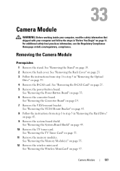
... B-CAS card. See "Removing the Back Cover" on page 23. 3 Follow the instructions from step 1 to step 3 in "Removing the Optical Drive" on page 19. 2 Remove the back cover. Camera Module 137 See "Removing the System-Board Shield" on page 25. 5 Remove the power...on page 43. 8 Follow the instructions from step 1 to step 5 in "Removing the Hard Drive" on page 11. For additional safety best practices information, see the Regulatory Compliance Homepage at dell.com/regulatory_compliance. Removing the Camera Module Prerequisites 1 Remove the stand. See "Removing the Memory ...
... B-CAS card. See "Removing the Back Cover" on page 23. 3 Follow the instructions from step 1 to step 3 in "Removing the Optical Drive" on page 19. 2 Remove the back cover. Camera Module 137 See "Removing the System-Board Shield" on page 25. 5 Remove the power...on page 43. 8 Follow the instructions from step 1 to step 5 in "Removing the Hard Drive" on page 11. For additional safety best practices information, see the Regulatory Compliance Homepage at dell.com/regulatory_compliance. Removing the Camera Module Prerequisites 1 Remove the stand. See "Removing the Memory ...
Owner's Manual (PDF)
Page 141
... VESA-mount bracket. Camera Module 141 See "Replacing the B-CAS card" on page 27. 21 Follow the instructions from step 4 to step 6 in "Replacing the Hard Drive" on page 39. 22 Replace the back cover. See "Replacing the Back Cover" on page 24. 23 Replace the stand.
... VESA-mount bracket. Camera Module 141 See "Replacing the B-CAS card" on page 27. 21 Follow the instructions from step 4 to step 6 in "Replacing the Hard Drive" on page 39. 22 Replace the back cover. See "Replacing the Back Cover" on page 24. 23 Replace the stand.
Owner's Manual (PDF)
Page 143
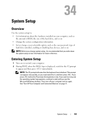
Entering System Setup 1 Turn on (or restart) your computer. 2 During POST, when the DELL logo is lost. See "Turn Off Your Computer and Connected Devices" on page 11. NOTE: The F2 prompt indicates that you write down the system ... Use the system setup to: • Get information about the hardware installed on your computer, such as the amount of RAM, the size of the hard drive, and so on • Change the system configuration information • Set or change a user-selectable option, such as the user password, type of...
Entering System Setup 1 Turn on (or restart) your computer. 2 During POST, when the DELL logo is lost. See "Turn Off Your Computer and Connected Devices" on page 11. NOTE: The F2 prompt indicates that you write down the system ... Use the system setup to: • Get information about the hardware installed on your computer, such as the amount of RAM, the size of the hard drive, and so on • Change the system configuration information • Set or change a user-selectable option, such as the user password, type of...
Owner's Manual (PDF)
Page 145
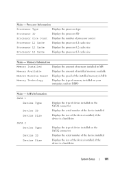
... memory installed on the SATA2 connector Displays the serial number of the device installed Displays the size of the device installed, if the device is a hard drive Displays the type of processor core(s) Processor L1 Cache Displays the processor L1 cache size Processor L2 Cache Displays the processor L2 cache size Processor... device installed on the SATA1 connector Displays the serial number of the device installed Displays the size of the device installed, if the device is a hard drive System Setup 145
... memory installed on the SATA2 connector Displays the serial number of the device installed Displays the size of the device installed, if the device is a hard drive Displays the type of processor core(s) Processor L1 Cache Displays the processor L1 cache size Processor L2 Cache Displays the processor L2 cache size Processor... device installed on the SATA1 connector Displays the serial number of the device installed Displays the size of the device installed, if the device is a hard drive System Setup 145
Owner's Manual (PDF)
Page 147
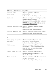
... or disable the computer from turning on automatically Enabled or Disabled (Disabled by default) SATA Mode Allows you to configure the behavior of the integrated hard-drive controller ATA Mode;
... or disable the computer from turning on automatically Enabled or Disabled (Disabled by default) SATA Mode Allows you to configure the behavior of the integrated hard-drive controller ATA Mode;
Owner's Manual (PDF)
Page 149
... errors during boot Report or Do Not Report (Report by default) Allows you to enable or disable booting from USB mass storage devices such as hard drive, optical drive, USB key, and so on Enable or Disable (Enabled by default) Specifies the boot sequence from the available devices Displays the first boot device...
... errors during boot Report or Do Not Report (Report by default) Allows you to enable or disable booting from USB mass storage devices such as hard drive, optical drive, USB key, and so on Enable or Disable (Enabled by default) Specifies the boot sequence from the available devices Displays the first boot device...
Owner's Manual (PDF)
Page 150
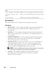
... feature allows you to a USB device, the device must be bootable. If no operating system is found on the drive, the computer generates an error message. • Hard Drive - If no operating system is in the lower-right corner of the screen, press . NOTE: To boot to ... port and restart the computer. The computer attempts to boot from the primary hard drive. The computer attempts to boot from the optical drive. The computer attempts to boot from the network. Boot Options • Diskette Drive - If no disc is on the network, the computer generates an error message...
... feature allows you to a USB device, the device must be bootable. If no operating system is found on the drive, the computer generates an error message. • Hard Drive - If no operating system is in the lower-right corner of the screen, press . NOTE: To boot to ... port and restart the computer. The computer attempts to boot from the primary hard drive. The computer attempts to boot from the optical drive. The computer attempts to boot from the network. Boot Options • Diskette Drive - If no disc is on the network, the computer generates an error message...


