Owner's Manual (PDF)
Page 9
31 Display Panel 123 Removing the Display Panel 123 Replacing the Display Panel 128 32 Infrared Sensor 131 Removing the Infrared Sensor 131 Replacing the Infrared Sensor 134 33 Camera Module 137 Removing the Camera Module 137 Replacing the Camera Module 140 34 System Setup 143 Overview 143 Entering System Setup 143 Clearing Forgotten Passwords 152 Clearing CMOS Settings 154 35 Flashing the BIOS 157 Contents 9
31 Display Panel 123 Removing the Display Panel 123 Replacing the Display Panel 128 32 Infrared Sensor 131 Removing the Infrared Sensor 131 Replacing the Infrared Sensor 134 33 Camera Module 137 Removing the Camera Module 137 Replacing the Camera Module 140 34 System Setup 143 Overview 143 Entering System Setup 143 Clearing Forgotten Passwords 152 Clearing CMOS Settings 154 35 Flashing the BIOS 157 Contents 9
Owner's Manual (PDF)
Page 11
... the computer turns off your computer. 5 After the computer is unplugged, press and hold the power button for shut-down instructions. 3 Disconnect your computer and all attached devices from the electrical outlets. 4 Disconnect all telephone cables, network cables, and attached devices from your computer. 1 Save and close all open files and exit all open programs before you are using a different operating system, see...
... the computer turns off your computer. 5 After the computer is unplugged, press and hold the power button for shut-down instructions. 3 Disconnect your computer and all attached devices from the electrical outlets. 4 Disconnect all telephone cables, network cables, and attached devices from your computer. 1 Save and close all open files and exit all open programs before you are using a different operating system, see...
Owner's Manual (PDF)
Page 12
... avoid bending any of the computer. CAUTION: To avoid damaging the components and cards, handle them evenly aligned to the power source. When connecting cables, ensure that you finish working inside the computer, replace all power sources before opening the computer cover or panels. For additional safety best practices information, see the Regulatory Compliance Homepage at the back of the components...
... avoid bending any of the computer. CAUTION: To avoid damaging the components and cards, handle them evenly aligned to the power source. When connecting cables, ensure that you finish working inside the computer, replace all power sources before opening the computer cover or panels. For additional safety best practices information, see the Regulatory Compliance Homepage at the back of the components...
Owner's Manual (PDF)
Page 13
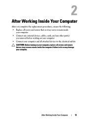
... your computer, replace all screws and ensure that no stray screws remain inside the computer. After Working Inside Your Computer After you complete the replacement procedures, ensure the following: • Replace all screws and ensure that no stray screws remain inside your computer • Connect any external devices, cables, cards, and any other part(s) you removed before working on your computer. After Working Inside Your Computer 13...
... your computer, replace all screws and ensure that no stray screws remain inside the computer. After Working Inside Your Computer After you complete the replacement procedures, ensure the following: • Replace all screws and ensure that no stray screws remain inside your computer • Connect any external devices, cables, cards, and any other part(s) you removed before working on your computer. After Working Inside Your Computer 13...
Owner's Manual (PDF)
Page 37
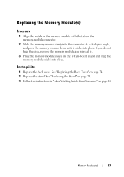
... the connector at a 45-degree angle, and press the memory module down until it . 3 Place the memory-module shield on page 13. See "Replacing the Stand" on page 21. 3 Follow the instructions in "After Working Inside Your Computer" on the system-board shield and snap the memory-module shield into place. If you do not hear the click, remove the memory...
... the connector at a 45-degree angle, and press the memory module down until it . 3 Place the memory-module shield on page 13. See "Replacing the Stand" on page 21. 3 Follow the instructions in "After Working Inside Your Computer" on the system-board shield and snap the memory-module shield into place. If you do not hear the click, remove the memory...
Owner's Manual (PDF)
Page 46
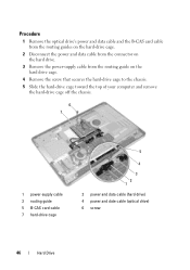
... the hard-drive cage. 2 Disconnect the power and data cable from the connector on the hard drive. 3 Remove the power-supply cable from the routing guide on the hard drive cage. 4 Remove the screw that secures the hard-drive cage to the chassis. 5 Slide the hard-drive cage toward the top of your computer and remove the hard-drive cage off the chassis. 6 7 1 power-supply cable 3 routing guide 5 B-CAS card cable 7 hard-drive cage 5 4 3 2 1 2 power and data cable (hard drive) 4 power and date cable (optical drive) 6 screw 46 Hard Drive
... the hard-drive cage. 2 Disconnect the power and data cable from the connector on the hard drive. 3 Remove the power-supply cable from the routing guide on the hard drive cage. 4 Remove the screw that secures the hard-drive cage to the chassis. 5 Slide the hard-drive cage toward the top of your computer and remove the hard-drive cage off the chassis. 6 7 1 power-supply cable 3 routing guide 5 B-CAS card cable 7 hard-drive cage 5 4 3 2 1 2 power and data cable (hard drive) 4 power and date cable (optical drive) 6 screw 46 Hard Drive
Owner's Manual (PDF)
Page 48
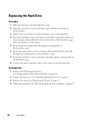
... connector on the hard drive. Postrequisites 1 Replace the VESA-mount bracket. Replacing the Hard Drive Procedure 1 Slide the hard drive into the slots on the chassis. 5 Route the power-supply cable through the routing guide on the hard-drive cage. 6 Route the optical drive's power and data cable and the B-CAS card cable through the routing guides on the hard-drive cage. 7 Route the hard-drive's power and data cable through the routing guide on the hard-drive cage. 8 Connect the power and data cable...
... connector on the hard drive. Postrequisites 1 Replace the VESA-mount bracket. Replacing the Hard Drive Procedure 1 Slide the hard drive into the slots on the chassis. 5 Route the power-supply cable through the routing guide on the hard-drive cage. 6 Route the optical drive's power and data cable and the B-CAS card cable through the routing guides on the hard-drive cage. 7 Route the hard-drive's power and data cable through the routing guide on the hard-drive cage. 8 Connect the power and data cable...

Owner's Manual (PDF)
Page 87
5 Slide the power port and power-supply control board through the slot on the I/O board shield. 6 Disconnect the power-supply fan cable and infrared cable from the system-board connectors. 7 Disconnect the antenna cable from the connector on the TV tuner card. 8 Lift the I/O board shield off the chassis. 1 2 3 4 5 1 I/O board shield 3 antenna cable 5 power-supply fan cable 2 TV tuner card 4 infrared cable I/O Board Shield 87
5 Slide the power port and power-supply control board through the slot on the I/O board shield. 6 Disconnect the power-supply fan cable and infrared cable from the system-board connectors. 7 Disconnect the antenna cable from the connector on the TV tuner card. 8 Lift the I/O board shield off the chassis. 1 2 3 4 5 1 I/O board shield 3 antenna cable 5 power-supply fan cable 2 TV tuner card 4 infrared cable I/O Board Shield 87
Owner's Manual (PDF)
Page 115
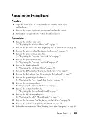
... 27. 9 Replace the power-supply fan bracket. See "Replacing the I/O Board Shield" on page 88. 7 Replace the I /O board shield. See "Replacing the B-CAS card" on page 75. 4 Replace the processor heat-sink fan. See "Replacing the Memory Module(s)" on page 13. See "Replacing the Stand" on page 21. 15 Follow the instructions in "After Working Inside Your Computer" on page 37. 11 Replace the system-board shield. See "Replacing the Wireless Mini-Card" on...
... 27. 9 Replace the power-supply fan bracket. See "Replacing the I/O Board Shield" on page 88. 7 Replace the I /O board shield. See "Replacing the B-CAS card" on page 75. 4 Replace the processor heat-sink fan. See "Replacing the Memory Module(s)" on page 13. See "Replacing the Stand" on page 21. 15 Follow the instructions in "After Working Inside Your Computer" on page 37. 11 Replace the system-board shield. See "Replacing the Wireless Mini-Card" on...
Owner's Manual (PDF)
Page 120
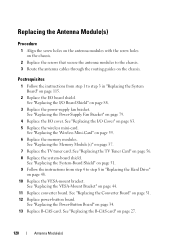
... "Replacing the B-CAS card" on page 88. 3 Replace the power-supply fan bracket. See "Replacing the I /O cover. See "Replacing the Wireless Mini-Card" on page 56. 8 Replace the system-board shield. See "Replacing the TV Tuner Card" on page 59. 6 Replace the memory modules. See "Replacing the Memory Module(s)" on page 83. 5 Replace the wireless mini-card. See "Replacing the System-Board Shield" on page 51. 9 Follow the instructions from step 1 to step 3 in "Replacing the Hard Drive...
... "Replacing the B-CAS card" on page 88. 3 Replace the power-supply fan bracket. See "Replacing the I /O cover. See "Replacing the Wireless Mini-Card" on page 56. 8 Replace the system-board shield. See "Replacing the TV Tuner Card" on page 59. 6 Replace the memory modules. See "Replacing the Memory Module(s)" on page 83. 5 Replace the wireless mini-card. See "Replacing the System-Board Shield" on page 51. 9 Follow the instructions from step 1 to step 3 in "Replacing the Hard Drive...
Owner's Manual (PDF)
Page 128
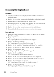
... power-supply unit. See "Replacing the Speakers" on page 71. 9 Replace the processor heat-sink. See "Replacing the I /O Board" on page 108. 11 Replace the speakers. See "Replacing the I /O Cover" on page 83. 15 Replace the B-CAS card. See "Replacing the I/O Board Shield" on page 59. 128 Display Panel See "Replacing the Wireless Mini-Card" on page 88. 14 Replace the I/O cover. Postrequisites 7 Follow the instructions from step 1 to the connector on the display panel. See "Replacing the Power-Supply Fan...
... power-supply unit. See "Replacing the Speakers" on page 71. 9 Replace the processor heat-sink. See "Replacing the I /O Board" on page 108. 11 Replace the speakers. See "Replacing the I /O Cover" on page 83. 15 Replace the B-CAS card. See "Replacing the I/O Board Shield" on page 59. 128 Display Panel See "Replacing the Wireless Mini-Card" on page 88. 14 Replace the I/O cover. Postrequisites 7 Follow the instructions from step 1 to the connector on the display panel. See "Replacing the Power-Supply Fan...
Owner's Manual (PDF)
Page 129
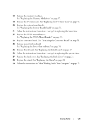
... 4 to step 8 in "After Working Inside Your Computer" on page 56. 20 Replace the system-board shield. See "Replacing the Power-Button Board" on page 24. 28 Replace the stand. Display Panel 129 18 Replace the memory modules. See "Replacing the Back Cover" on page 34. 25 Replace B-CAS card. See "Replacing the Stand" on page 21. 29 Follow the instructions in replacing the hard-drive 22 Replace the VESA-mount bracket. See...
... 4 to step 8 in "After Working Inside Your Computer" on page 56. 20 Replace the system-board shield. See "Replacing the Power-Button Board" on page 24. 28 Replace the stand. Display Panel 129 18 Replace the memory modules. See "Replacing the Back Cover" on page 34. 25 Replace B-CAS card. See "Replacing the Stand" on page 21. 29 Follow the instructions in replacing the hard-drive 22 Replace the VESA-mount bracket. See...
Owner's Manual (PDF)
Page 134
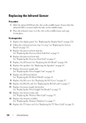
... Replace the memory modules. See "Replacing the Wireless Mini-Card" on page 63. 7 Replace the power-supply unit. See "Replacing the Power-Supply Unit" on page 91. 8 Replace the I /O cover. See "Replacing the Memory Module(s)" on page 27. 11 Replace the power-supply fan bracket. See "Replacing the I/O Board Shield" on the middle frame. See "Replacing the B-CAS card" on page 37. 14 Replace the TV tuner card. See "Replacing the Display Panel" on page 128. 2 Follow the instructions...
... Replace the memory modules. See "Replacing the Wireless Mini-Card" on page 63. 7 Replace the power-supply unit. See "Replacing the Power-Supply Unit" on page 91. 8 Replace the I /O cover. See "Replacing the Memory Module(s)" on page 27. 11 Replace the power-supply fan bracket. See "Replacing the I/O Board Shield" on the middle frame. See "Replacing the B-CAS card" on page 37. 14 Replace the TV tuner card. See "Replacing the Display Panel" on page 128. 2 Follow the instructions...
Owner's Manual (PDF)
Page 140
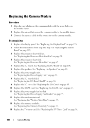
... I /O board. See "Replacing the TV Tuner Card" on page 115. 3 Replace the processor heat-sink fan. See "Replacing the Display Panel" on page 128. 2 Follow the instructions from step 1 to the connector on page 108. 6 Replace the speakers. See "Replacing the B-CAS card" on page 59. 13 Replace the memory modules. See "Replacing the Wireless Mini-Card" on page 27. 11 Replace the power-supply fan bracket. See "Replacing the Memory Module(s)" on page 67. 5 Replace the I /O Board...
... I /O board. See "Replacing the TV Tuner Card" on page 115. 3 Replace the processor heat-sink fan. See "Replacing the Display Panel" on page 128. 2 Follow the instructions from step 1 to the connector on page 108. 6 Replace the speakers. See "Replacing the B-CAS card" on page 59. 13 Replace the memory modules. See "Replacing the Wireless Mini-Card" on page 27. 11 Replace the power-supply fan bracket. See "Replacing the Memory Module(s)" on page 67. 5 Replace the I /O Board...
Owner's Manual (PDF)
Page 143
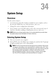
... POST, when the DELL logo is displayed, watch for future reference. System Setup Overview Use the system setup to: • Get information about the hardware installed on your computer, such as the amount of RAM, the size of the hard drive, and so on • Change the system configuration information • Set or change a user-selectable option, such as the user password, type of hard drive installed, enabling or disabling base devices, and so on...
... POST, when the DELL logo is displayed, watch for future reference. System Setup Overview Use the system setup to: • Get information about the hardware installed on your computer, such as the amount of RAM, the size of the hard drive, and so on • Change the system configuration information • Set or change a user-selectable option, such as the user password, type of hard drive installed, enabling or disabling base devices, and so on...
Owner's Manual (PDF)
Page 145
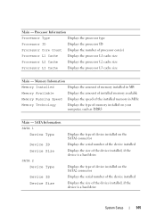
... speed of the installed memory in MHz Memory Technology Displays the type of processor core(s) Processor L1 Cache Displays the processor L1 cache size Processor L2 Cache Displays the processor L2 cache size Processor L3 Cache Displays the processor L3 cache size Main - Processor Information Processor Type Displays the processor type Processor ID Displays the processor ID Processor Core Count Displays the number of memory installed on the SATA2 connector Displays the serial number of the device installed Displays the size of the device installed, if the device is a hard drive...
... speed of the installed memory in MHz Memory Technology Displays the type of processor core(s) Processor L1 Cache Displays the processor L1 cache size Processor L2 Cache Displays the processor L2 cache size Processor L3 Cache Displays the processor L3 cache size Main - Processor Information Processor Type Displays the processor type Processor ID Displays the processor ID Processor Core Count Displays the number of memory installed on the SATA2 connector Displays the serial number of the device installed Displays the size of the device installed, if the device is a hard drive...
Owner's Manual (PDF)
Page 147
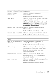
... audio controller Enabled or Disable (Enabled by default) SATA Mode Allows you to enable or disable the computer from a power failure Power Off, Power On, or Last Power State (Power Off by default) DeepSx Power Policies Allows you to configure the behavior of the integrated hard-drive controller ATA Mode; AHCI Mode (AHCI Mode by default) CAUTION: Changing the SATA Mode may prevent booting of your computer after it recovers from turning on by LAN/WLAN special LAN or wireless LAN signals Enabled or Disabled (Disabled by default) AC Recovery...
... audio controller Enabled or Disable (Enabled by default) SATA Mode Allows you to enable or disable the computer from a power failure Power Off, Power On, or Last Power State (Power Off by default) DeepSx Power Policies Allows you to configure the behavior of the integrated hard-drive controller ATA Mode; AHCI Mode (AHCI Mode by default) CAUTION: Changing the SATA Mode may prevent booting of your computer after it recovers from turning on by LAN/WLAN special LAN or wireless LAN signals Enabled or Disabled (Disabled by default) AC Recovery...
Owner's Manual (PDF)
Page 149
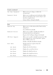
...) Set User Password Password Check Boot Numlock Key Keyboard Errors USB Boot Support Boot Mode 1st Boot 2nd Boot 3rd Boot 4th Boot 5th Boot Allows you to set, change, or delete the user password Allows you to enable password verification either when you attempt to enter system setup or each time the computer boots Setup or Always (Setup by default) Allows you to set the status of the Num Lock key during boot On or Off (On by default) Allows you to enable or disable...
...) Set User Password Password Check Boot Numlock Key Keyboard Errors USB Boot Support Boot Mode 1st Boot 2nd Boot 3rd Boot 4th Boot 5th Boot Allows you to set, change, or delete the user password Allows you to enable password verification either when you attempt to enter system setup or each time the computer boots Setup or Always (Setup by default) Allows you to set the status of the Num Lock key during boot On or Off (On by default) Allows you to enable or disable...
Owner's Manual (PDF)
Page 150
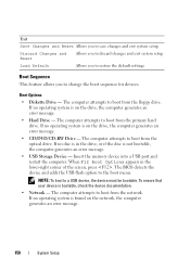
... changes and exit system setup Discard Changes and Reset Allows you to discard changes and exit system setup Load Default Allows you to restore the default settings Boot Sequence This feature allows you to the boot menu. Boot Options • Diskette Drive - Insert the memory device into a USB port and restart the computer. The BIOS detects the device and adds the USB flash option to change the boot sequence for devices. The computer attempts to boot from the network. When F12 Boot Options...
... changes and exit system setup Discard Changes and Reset Allows you to discard changes and exit system setup Load Default Allows you to restore the default settings Boot Sequence This feature allows you to the boot menu. Boot Options • Diskette Drive - Insert the memory device into a USB port and restart the computer. The BIOS detects the device and adds the USB flash option to change the boot sequence for devices. The computer attempts to boot from the network. When F12 Boot Options...
Owner's Manual (PDF)
Page 151
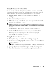
... Boot menu option and press to run Dell Diagnostics from . For example, if you are booting from a USB device, connect the USB device to boot from the Drivers and Utilities disc. NOTE: Write down your computer. 3 When F2 Setup, F12 Boot Options appears in case you see the Microsoft Windows desktop. The previous boot sequence is restored at the next boot. 1 If you want to a USB memory key, highlight USB Storage Device and press . The Boot Device Menu appears, listing all available boot devices. 4 On the Boot Device Menu...
... Boot menu option and press to run Dell Diagnostics from . For example, if you are booting from a USB device, connect the USB device to boot from the Drivers and Utilities disc. NOTE: Write down your computer. 3 When F2 Setup, F12 Boot Options appears in case you see the Microsoft Windows desktop. The previous boot sequence is restored at the next boot. 1 If you want to a USB memory key, highlight USB Storage Device and press . The Boot Device Menu appears, listing all available boot devices. 4 On the Boot Device Menu...


