
Owners Manual
Page 3
Contents 1 Before You Begin 11 Recommended Tools 11 Turning Off Your Computer 11 Safety Instructions 11 2 Technical Overview 15 Inside View of Your Inspiron One 15 System Board Components 17 3 Back Cover 19 Removing the Back Cover 19 Replacing the Back Cover 21 4 Hard Drive 23 Removing the Hard Drive 23 Replacing the Hard Drive 25 5 Optical Drive 27 Removing the Optical Drive 27 Contents 3
Contents 1 Before You Begin 11 Recommended Tools 11 Turning Off Your Computer 11 Safety Instructions 11 2 Technical Overview 15 Inside View of Your Inspiron One 15 System Board Components 17 3 Back Cover 19 Removing the Back Cover 19 Replacing the Back Cover 21 4 Hard Drive 23 Removing the Hard Drive 23 Replacing the Hard Drive 25 5 Optical Drive 27 Removing the Optical Drive 27 Contents 3
Owners Manual
Page 11
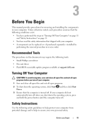
... Ensure that shipped with your computer. • A component can be replaced or-if purchased separately-installed by performing the removal procedure in "Turning Off Your Computer" on page 11 and "Safety Instructions" on page 11. • You have performed the steps in reverse order. Unless otherwise... require the following tools: • Small Phillips screwdriver • Hex nut driver • Flash BIOS executable update program available at support.dell.com Turning Off Your Computer CAUTION: To avoid losing data, save and close all open files and exit all open programs. 2 To shut down...
... Ensure that shipped with your computer. • A component can be replaced or-if purchased separately-installed by performing the removal procedure in "Turning Off Your Computer" on page 11 and "Safety Instructions" on page 11. • You have performed the steps in reverse order. Unless otherwise... require the following tools: • Small Phillips screwdriver • Hex nut driver • Flash BIOS executable update program available at support.dell.com Turning Off Your Computer CAUTION: To avoid losing data, save and close all open files and exit all open programs. 2 To shut down...
Owners Manual
Page 12
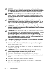
..., not on page 11. After the installation is flat and clean to prevent the computer display from being scratched. 2 Turn off your computer and all attached devices from their electrical outlets. 5 Disconnect all attached devices. For additional safety best practices... information, see the Regulatory Compliance Homepage at dell.com/regulatory_compliance. Some cables have connectors with your computer. See "Turning Off Your Computer" on the cable itself. WARNING: Before working inside your computer, read the...
..., not on page 11. After the installation is flat and clean to prevent the computer display from being scratched. 2 Turn off your computer and all attached devices from their electrical outlets. 5 Disconnect all attached devices. For additional safety best practices... information, see the Regulatory Compliance Homepage at dell.com/regulatory_compliance. Some cables have connectors with your computer. See "Turning Off Your Computer" on the cable itself. WARNING: Before working inside your computer, read the...
Owners Manual
Page 21
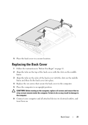
.... 5 Place the computer in an upright position. Replacing the Back Cover 1 Follow the instructions in a secure location. CAUTION: Before turning on the computer, replace all attached devices to electrical outlets, and turn them on the middle frame and then fix the back cover into place. 4 Replace the six screws that secure the...
.... 5 Place the computer in an upright position. Replacing the Back Cover 1 Follow the instructions in a secure location. CAUTION: Before turning on the computer, replace all attached devices to electrical outlets, and turn them on the middle frame and then fix the back cover into place. 4 Replace the six screws that secure the...
Owners Manual
Page 23
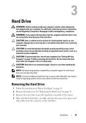
... Damage due to install an operating system, drivers, and utilities on the new hard drive. CAUTION: To prevent data loss, turn off your computer. NOTE: Dell does not guarantee compatibility or provide support for hard drives from the computer when the drive is hot, do not touch the ... sources other than Dell. Do not remove the hard drive while the computer is not covered by periodically touching an unpainted metal surface (such as a connector on page 11) before removing the hard drive. Hard Drive 23 For additional safety best practices information, see "Turning Off Your Computer"...
... Damage due to install an operating system, drivers, and utilities on the new hard drive. CAUTION: To prevent data loss, turn off your computer. NOTE: Dell does not guarantee compatibility or provide support for hard drives from the computer when the drive is hot, do not touch the ... sources other than Dell. Do not remove the hard drive while the computer is not covered by periodically touching an unpainted metal surface (such as a connector on page 11) before removing the hard drive. Hard Drive 23 For additional safety best practices information, see "Turning Off Your Computer"...
Owners Manual
Page 26
Failure to do so may result in damage to the computer. 8 Connect your computer and all attached devices to electrical outlets, and turn them on the computer, replace all screws and ensure that no stray screws remain inside the computer. CAUTION: Before turning on . 26 Hard Drive
Failure to do so may result in damage to the computer. 8 Connect your computer and all attached devices to electrical outlets, and turn them on the computer, replace all screws and ensure that no stray screws remain inside the computer. CAUTION: Before turning on . 26 Hard Drive
Owners Manual
Page 29
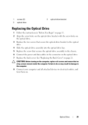
... optical-drive bay. 5 Replace the screw that secures the optical-drive assembly to the chassis. 6 Connect the power and data cables to electrical outlets, and turn them on the computer, replace all screws and ensure that no stray screws remain inside the computer. CAUTION: Before...
... optical-drive bay. 5 Replace the screw that secures the optical-drive assembly to the chassis. 6 Connect the power and data cables to electrical outlets, and turn them on the computer, replace all screws and ensure that no stray screws remain inside the computer. CAUTION: Before...
Owners Manual
Page 33
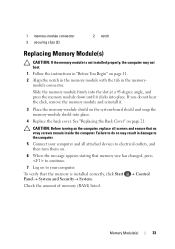
... the memory module down until it . 3 Place the memory-module shield on the computer, replace all attached devices to electrical outlets, and then turn them on. 6 When the message appears stating that memory size has changed, press to continue. 7 Log on to your computer and all screws...module and reinstall it clicks into place. 4 Replace the back cover. To verify that no stray screws remain inside the computer. CAUTION: Before turning on the system-board shield and snap the memory-module shield into place. Check the amount of memory (RAM) listed. Control ...
... the memory module down until it . 3 Place the memory-module shield on the computer, replace all attached devices to electrical outlets, and then turn them on. 6 When the message appears stating that memory size has changed, press to continue. 7 Log on to your computer and all screws...module and reinstall it clicks into place. 4 Replace the back cover. To verify that no stray screws remain inside the computer. CAUTION: Before turning on the system-board shield and snap the memory-module shield into place. Check the amount of memory (RAM) listed. Control ...
Owners Manual
Page 36
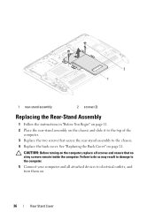
... so may result in "Before You Begin" on page 11. 2 Place the rear-stand assembly on the chassis and slide it to electrical outlets, and turn them on. 36 Rear Stand Cover CAUTION: Before...
... so may result in "Before You Begin" on page 11. 2 Place the rear-stand assembly on the chassis and slide it to electrical outlets, and turn them on. 36 Rear Stand Cover CAUTION: Before...
Owners Manual
Page 38
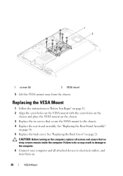
CAUTION: Before turning on the chassis. 3 Replace the six screws that no stray screws remain inside the computer. Replacing the VESA Mount 1 Follow the instructions in damage to ... the computer, replace all screws and ensure that secure the VESA mount to the chassis. 4 Replace the rear-stand assembly. Failure to electrical outlets, and turn them on page 36. 5 Replace the back cover. See "Replacing the Rear-Stand Assembly" on . 38 VESA Mount 1 2 1 screws (6) 2 VESA mount 5 Lift the VESA mount...
CAUTION: Before turning on the chassis. 3 Replace the six screws that no stray screws remain inside the computer. Replacing the VESA Mount 1 Follow the instructions in damage to ... the computer, replace all screws and ensure that secure the VESA mount to the chassis. 4 Replace the rear-stand assembly. Failure to electrical outlets, and turn them on page 36. 5 Replace the back cover. See "Replacing the Rear-Stand Assembly" on . 38 VESA Mount 1 2 1 screws (6) 2 VESA mount 5 Lift the VESA mount...
Owners Manual
Page 40
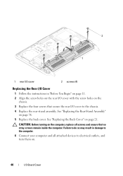
... "Before You Begin" on page 11. 2 Align the screw holes on the rear I/O cover with the screw holes on . 40 I /O cover to electrical outlets, and turn them on the chassis. 3 Replace the four screws that no stray screws remain inside the computer. 2 1 1 rear I/O cover 2 screws (4) Replacing the Rear I/O Cover 1 Follow... the instructions in damage to the computer. 6 Connect your computer and all screws and ensure that secure the rear I /O Board Cover CAUTION: Before turning on the computer, replace all attached devices to the chassis. 4 Replace the rear-stand assembly.
... "Before You Begin" on page 11. 2 Align the screw holes on the rear I/O cover with the screw holes on . 40 I /O cover to electrical outlets, and turn them on the chassis. 3 Replace the four screws that no stray screws remain inside the computer. 2 1 1 rear I/O cover 2 screws (4) Replacing the Rear I/O Cover 1 Follow... the instructions in damage to the computer. 6 Connect your computer and all screws and ensure that secure the rear I /O Board Cover CAUTION: Before turning on the computer, replace all attached devices to the chassis. 4 Replace the rear-stand assembly.
Owners Manual
Page 41
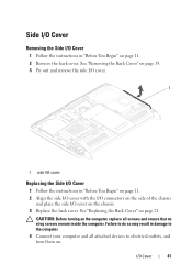
See "Replacing the Back Cover" on . Failure to do so may result in damage to electrical outlets, and turn them on page 21. I/O Cover 41 CAUTION: Before turning on the chassis. 3 Replace the back cover. See "Removing the Back Cover" on page 19. 3 Pry out and remove the side I/O cover. 1 1 side I/O cover Replacing...
See "Replacing the Back Cover" on . Failure to do so may result in damage to electrical outlets, and turn them on page 21. I/O Cover 41 CAUTION: Before turning on the chassis. 3 Replace the back cover. See "Removing the Back Cover" on page 19. 3 Pry out and remove the side I/O cover. 1 1 side I/O cover Replacing...
Owners Manual
Page 45
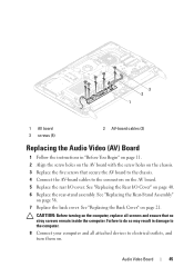
... computer. 8 Connect your computer and all screws and ensure that no stray screws remain inside the computer. CAUTION: Before turning on the computer, replace all attached devices to electrical outlets, and turn them on. Audio Video Board 45 Failure to do so may result in "Before You Begin" on page 11. 2 Align...
... computer. 8 Connect your computer and all screws and ensure that no stray screws remain inside the computer. CAUTION: Before turning on the computer, replace all attached devices to electrical outlets, and turn them on. Audio Video Board 45 Failure to do so may result in "Before You Begin" on page 11. 2 Align...
Owners Manual
Page 49
CAUTION: Before turning on . Failure to do so may result in damage to the computer. 9 Connect your computer and all attached devices to electrical outlets, and turn them on the computer, replace all screws and ensure that no stray screws remain inside the computer. Main Chassis 49
CAUTION: Before turning on . Failure to do so may result in damage to the computer. 9 Connect your computer and all attached devices to electrical outlets, and turn them on the computer, replace all screws and ensure that no stray screws remain inside the computer. Main Chassis 49
Owners Manual
Page 52
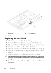
... with the screw hole on the chassis. 4 Replace the screw that no stray screws remain inside the computer. See "Replacing the Rear I /O cover. CAUTION: Before turning on page 21. See "Replacing the Rear-Stand Assembly" on page 40. 6 Replace the rear-stand assembly. See "Replacing the Back Cover" on the computer... 1 Follow the instructions in damage to the computer. 8 Connect your computer and all screws and ensure that secures the B-CAS card to electrical outlets, and turn them on. 52 B-CAS Card
... with the screw hole on the chassis. 4 Replace the screw that no stray screws remain inside the computer. See "Replacing the Rear I /O cover. CAUTION: Before turning on page 21. See "Replacing the Rear-Stand Assembly" on page 40. 6 Replace the rear-stand assembly. See "Replacing the Back Cover" on the computer... 1 Follow the instructions in damage to the computer. 8 Connect your computer and all screws and ensure that secures the B-CAS card to electrical outlets, and turn them on. 52 B-CAS Card

Owners Manual
Page 54
..." on page 41. 5 Replace the rear I /O Cover" on page 40. 54 System-Board Shield 1 2 1 system-board shield 2 screws (5) 7 Pry away the system-board shield and turn it over the system board. 3 Align the screw holes on the system-board shield with the side I/O connectors on the chassis and place the system...
..." on page 41. 5 Replace the rear I /O Cover" on page 40. 54 System-Board Shield 1 2 1 system-board shield 2 screws (5) 7 Pry away the system-board shield and turn it over the system board. 3 Align the screw holes on the system-board shield with the side I/O connectors on the chassis and place the system...
Owners Manual
Page 55
See "Replacing the Back Cover" on the computer, replace all attached devices to electrical outlets, and turn them on page 36. 7 Replace the back cover. System-Board Shield 55 CAUTION: Before turning on page 21. See "Replacing the Rear-Stand Assembly" on . Failure to do so may result in damage to the computer. 8 Connect your computer and all screws and ensure that no stray screws remain inside the computer. 6 Replace the rear-stand assembly.
See "Replacing the Back Cover" on the computer, replace all attached devices to electrical outlets, and turn them on page 36. 7 Replace the back cover. System-Board Shield 55 CAUTION: Before turning on page 21. See "Replacing the Rear-Stand Assembly" on . Failure to do so may result in damage to the computer. 8 Connect your computer and all screws and ensure that no stray screws remain inside the computer. 6 Replace the rear-stand assembly.
Owners Manual
Page 59
... Battery 59 See "Replacing the Back Cover" on the computer, replace all screws and ensure that no stray screws remain inside the computer. CAUTION: Before turning on page 21. See "Replacing the Rear I/O Cover" on page 41. 6 Replace the rear-stand assembly. See "Replacing the Side I/O Cover" on page 40. 5 ...Replace the side I /O cover. Failure to do so may result in damage to the computer. 8 Connect your computer and devices to electrical outlets, and then turn them on. 9 Enter the system setup and restore the settings you recorded in step 1. 4 Replace the rear I /O cover.
... Battery 59 See "Replacing the Back Cover" on the computer, replace all screws and ensure that no stray screws remain inside the computer. CAUTION: Before turning on page 21. See "Replacing the Rear I/O Cover" on page 41. 6 Replace the rear-stand assembly. See "Replacing the Side I/O Cover" on page 40. 5 ...Replace the side I /O cover. Failure to do so may result in damage to the computer. 8 Connect your computer and devices to electrical outlets, and then turn them on. 9 Enter the system setup and restore the settings you recorded in step 1. 4 Replace the rear I /O cover.
Owners Manual
Page 63
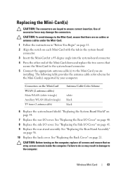
... page 21. CAUTION: To avoid damage to ensure correct insertion. Wireless Mini-Card 63 Replacing the Mini-Card(s) CAUTION: The connectors are installing. CAUTION: Before turning on page 54. 7 Replace the rear I/O cover. "Replacing the System-Board Shield" on the computer, replace all screws and ensure that secure the Mini-Card...
... page 21. CAUTION: To avoid damage to ensure correct insertion. Wireless Mini-Card 63 Replacing the Mini-Card(s) CAUTION: The connectors are installing. CAUTION: Before turning on page 54. 7 Replace the rear I/O cover. "Replacing the System-Board Shield" on the computer, replace all screws and ensure that secure the Mini-Card...
Owners Manual
Page 64
11 Connect your computer and all attached devices to electrical outlets, and turn them on. 64 Wireless Mini-Card
11 Connect your computer and all attached devices to electrical outlets, and turn them on. 64 Wireless Mini-Card


