
Owner's Manual
Page 95
... message is most likely to occur after a memory module is trying to boot to a nonbootable CD. KEYBOARD CLOCK LINE FAILURE - A memory module may be played. Reinstall the memory modules and, if necessary, replace them. See "Dell Diagnostics" on page 87. Shut down the computer, reinstall the hard drive, and restart the computer. If...
... message is most likely to occur after a memory module is trying to boot to a nonbootable CD. KEYBOARD CLOCK LINE FAILURE - A memory module may be played. Reinstall the memory modules and, if necessary, replace them. See "Dell Diagnostics" on page 87. Shut down the computer, reinstall the hard drive, and restart the computer. If...

Owner's Manual
Page 97
...replaced. P L E A S E R U N T H E S YS T E M S E T U P P R O G R A M - The time or date stored in the Dell Diagnostics. TIMER CHIP COUNTER 2 FAILED - See "Dell Diagnostics" on page 87. X : \ I S N O T A C C E S S I C E - Replace ...section, follow the safety instructions in the Product Information Guide. TI M E - Correct the settings for the Date and Time options. U N E X P E C T E D I N T E R R U P T I S CRITICALLY LOW - The keyboard controller may be malfunctioning, or a memory module may be loose. I F Y O U H A V E P R O B L E M S W I T H A N I E E E 1 3 9 4 D E V I C E...
...replaced. P L E A S E R U N T H E S YS T E M S E T U P P R O G R A M - The time or date stored in the Dell Diagnostics. TIMER CHIP COUNTER 2 FAILED - See "Dell Diagnostics" on page 87. X : \ I S N O T A C C E S S I C E - Replace ...section, follow the safety instructions in the Product Information Guide. TI M E - Correct the settings for the Date and Time options. U N E X P E C T E D I N T E R R U P T I S CRITICALLY LOW - The keyboard controller may be malfunctioning, or a memory module may be loose. I F Y O U H A V E P R O B L E M S W I T H A N I E E E 1 3 9 4 D E V I C E...
Owner's Manual
Page 131
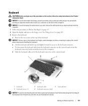
... display and remove the hinge cover. Adding and Replacing Parts 131 Be careful when removing and handling the keyboard. d Slide the keyboard cable out of the keyboard connector on the system board. 1 2 5 3 4 1 keyboard 2 keyboard screws (2) 3 keyboard cable 5 keyboard tabs 4 keyboard connector latch NOTICE: To avoid scratching the palm rest when replacing the keyboard, hook the five tabs along the front edge...
... display and remove the hinge cover. Adding and Replacing Parts 131 Be careful when removing and handling the keyboard. d Slide the keyboard cable out of the keyboard connector on the system board. 1 2 5 3 4 1 keyboard 2 keyboard screws (2) 3 keyboard cable 5 keyboard tabs 4 keyboard connector latch NOTICE: To avoid scratching the palm rest when replacing the keyboard, hook the five tabs along the front edge...
Owner's Manual
Page 132
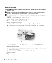
... a wrist grounding strap or by periodically touching an unpainted metal surface (such as a connector on page 129. 3 Remove the keyboard. NOTICE: To avoid damaging the system board, you must remove the battery before you begin working inside the computer. 1 Follow the... 2 release latch 3 battery cable connector 5 Install the replacement battery: a Insert the battery at a 30-degree angle under the release latch with the positive side up on the system board. 6 Replace the keyboard. 7 Replace the hinge cover. 132 Adding and Replacing Parts b Connect the battery cable to the connector on ...
... a wrist grounding strap or by periodically touching an unpainted metal surface (such as a connector on page 129. 3 Remove the keyboard. NOTICE: To avoid damaging the system board, you must remove the battery before you begin working inside the computer. 1 Follow the... 2 release latch 3 battery cable connector 5 Install the replacement battery: a Insert the battery at a 30-degree angle under the release latch with the positive side up on the system board. 6 Replace the keyboard. 7 Replace the hinge cover. 132 Adding and Replacing Parts b Connect the battery cable to the connector on ...
Owner's Manual
Page 151
... attached devices from the computer and from the display. Only use compressed air to boot and press . See "Turning Off Your Computer" on the keyboard and to seep between the touch pad and the surrounding palm rest. Never touch the lens in the drive. CDs and DVDs NOTICE: Always use... the Product Information Guide. Do not allow water from the cloth to the edges until it gently across the surface of the touch pad. See "Replacing the Battery" on page 47. 4 Moisten a soft, lint-free cloth with water. Clean your computer with a soft cloth dampened with water, and wipe it ...
... attached devices from the computer and from the display. Only use compressed air to boot and press . See "Turning Off Your Computer" on the keyboard and to seep between the touch pad and the surrounding palm rest. Never touch the lens in the drive. CDs and DVDs NOTICE: Always use... the Product Information Guide. Do not allow water from the cloth to the edges until it gently across the surface of the touch pad. See "Replacing the Battery" on page 47. 4 Moisten a soft, lint-free cloth with water. Clean your computer with a soft cloth dampened with water, and wipe it ...
Owner's Manual
Page 184
...floppy drive connecting to a USB connector, 20 H hard drive description, 27 problems, 92 replacing, 119 returning to Dell, 121 hardware conflicts, 110 Dell Diagnostics, 87 Hardware Troubleshooter, 110 Help and Support Center, 13-14 hibernate mode, 46 hinge... cover description, 129 removing, 129 I icons adjusting the size, 49 IEEE 1394 connector description, 21 problems, 97 Internet connection, 29 Internet Connection Firewall, 84 IRQ conflicts, 110 K keyboard...
...floppy drive connecting to a USB connector, 20 H hard drive description, 27 problems, 92 replacing, 119 returning to Dell, 121 hardware conflicts, 110 Dell Diagnostics, 87 Hardware Troubleshooter, 110 Help and Support Center, 13-14 hibernate mode, 46 hinge... cover description, 129 removing, 129 I icons adjusting the size, 49 IEEE 1394 connector description, 21 problems, 97 Internet connection, 29 Internet Connection Firewall, 84 IRQ conflicts, 110 K keyboard...


