Owner's Manual
Page 7
Resolving Software and Hardware Incompatibilities 91 Restoring Your Operating System 92 Using Microsoft Windows System Restore . . . . 93 Using Dell PC Restore 95 Using the Operating System CD 98 4 Removing and Installing Parts 101 Before You Begin 101 Recommended Tools 101 Turning Off Your Computer 102 Before Working Inside Your Computer 102 Removing the...
Resolving Software and Hardware Incompatibilities 91 Restoring Your Operating System 92 Using Microsoft Windows System Restore . . . . 93 Using Dell PC Restore 95 Using the Operating System CD 98 4 Removing and Installing Parts 101 Before You Begin 101 Recommended Tools 101 Turning Off Your Computer 102 Before Working Inside Your Computer 102 Removing the...
Owner's Manual
Page 55
Troubleshooting Tips Follow these tips when you troubleshoot your computer: • If you added or removed a part before the problem started, review the installation procedures and ensure that the device is incorrectly installed. Discard used batteries according to... service technician only and are not custom replaceable. If the battery still does not work , ensure that the part is correctly installed. • If a peripheral device does not work properly, contact Dell (see "Getting Help" on page 183). This message may be replaceable by the manufacturer. Solving Problems CAUTION:...
Troubleshooting Tips Follow these tips when you troubleshoot your computer: • If you added or removed a part before the problem started, review the installation procedures and ensure that the device is incorrectly installed. Discard used batteries according to... service technician only and are not custom replaceable. If the battery still does not work , ensure that the part is correctly installed. • If a peripheral device does not work properly, contact Dell (see "Getting Help" on page 183). This message may be replaceable by the manufacturer. Solving Problems CAUTION:...

Owner's Manual
Page 101
...Guide. • A component can be replaceable by a certified service technician only and are not custom replaceable. Removing and Installing Parts CAUTION: To guard against electrical shock, laceration by performing the removal procedure in reverse order. CAUTION: Do not operate your ...computer with any cover(s) (including computer covers, bezels, filler brackets, front-panel inserts, and so on the Dell Support website at support.dell.com Removing and Installing Parts 101 Unless otherwise noted, each procedure assumes that the following tools: • Small flat-blade screwdriver • ...
...Guide. • A component can be replaceable by a certified service technician only and are not custom replaceable. Removing and Installing Parts CAUTION: To guard against electrical shock, laceration by performing the removal procedure in reverse order. CAUTION: Do not operate your ...computer with any cover(s) (including computer covers, bezels, filler brackets, front-panel inserts, and so on the Dell Support website at support.dell.com Removing and Installing Parts 101 Unless otherwise noted, each procedure assumes that the following tools: • Small flat-blade screwdriver • ...
Owner's Manual
Page 102
... computer and any attached devices are turned off . NOTICE: Handle components and cards with care. Damage due to ensure your warranty. 102 Removing and Installing Parts Windows® XP: 1 Save and close any open files and exit any open programs. 2 Click Start→ Turn Off Computer→ Turn off . ...system, press and hold the power button for at least 8 to 10 seconds until the computer turns off . 3 Ensure that is not authorized by Dell is not covered by its pins. Turning Off Your Computer NOTICE: To avoid losing data, save and close any open files and exit any open...
... computer and any attached devices are turned off . NOTICE: Handle components and cards with care. Damage due to ensure your warranty. 102 Removing and Installing Parts Windows® XP: 1 Save and close any open files and exit any open programs. 2 Click Start→ Turn Off Computer→ Turn off . ...system, press and hold the power button for at least 8 to 10 seconds until the computer turns off . 3 Ensure that is not authorized by Dell is not covered by its pins. Turning Off Your Computer NOTICE: To avoid losing data, save and close any open files and exit any open...
Owner's Manual
Page 103
..., laceration by touching an unpainted metal surface, such as the metal at the back of cable, press in the Product Information Guide. Removing and Installing Parts 103 Also, before you disconnect the cable. NOTICE: Ensure that both connectors are disconnecting this section, follow the safety instructions in on the locking tabs...
..., laceration by touching an unpainted metal surface, such as the metal at the back of cable, press in the Product Information Guide. Removing and Installing Parts 103 Also, before you disconnect the cable. NOTICE: Ensure that both connectors are disconnecting this section, follow the safety instructions in on the locking tabs...
Owner's Manual
Page 104
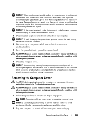
... the cover, using a flat-blade screwdriver. 1 2 1 computer cover 2 screws (2) 4 Release the computer cover by lifting the card retention release lever up. 104 Removing and Installing Parts
... the cover, using a flat-blade screwdriver. 1 2 1 computer cover 2 screws (2) 4 Release the computer cover by lifting the card retention release lever up. 104 Removing and Installing Parts
Owner's Manual
Page 105
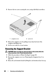
4 Remove any cable(s) attached to the support bracket. 5 Pivot the support bracket and lift it off the hinge tabs. 6 Set it aside in a secure location. 3 1 2 1 support bracket 2 card retention bracket 3 card retention release lever Removing and Installing Parts 105
4 Remove any cable(s) attached to the support bracket. 5 Pivot the support bracket and lift it off the hinge tabs. 6 Set it aside in a secure location. 3 1 2 1 support bracket 2 card retention bracket 3 card retention release lever Removing and Installing Parts 105

Owner's Manual
Page 106
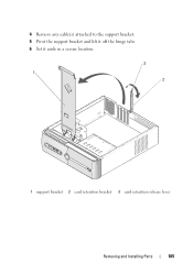
Inside View of Your Computer CAUTION: Before you begin any of the procedures in this section, follow the safety instructions in the Product Information Guide. 1 2 3 6 4 5 1 power supply 2 hard drive 3 front I/O panel 4 floppy drive or Media 5 CD or DVD drive 6 chassis fan Card Reader (optional) 106 Removing and Installing Parts
Inside View of Your Computer CAUTION: Before you begin any of the procedures in this section, follow the safety instructions in the Product Information Guide. 1 2 3 6 4 5 1 power supply 2 hard drive 3 front I/O panel 4 floppy drive or Media 5 CD or DVD drive 6 chassis fan Card Reader (optional) 106 Removing and Installing Parts
Owner's Manual
Page 107
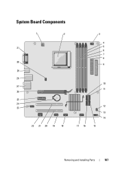
System Board Components 1 2 31 30 29 28 27 26 25 24 23 22 21 20 19 18 3 4 5 6 7 8 9 10 11 17 16 12 13 14 15 Removing and Installing Parts 107
System Board Components 1 2 31 30 29 28 27 26 25 24 23 22 21 20 19 18 3 4 5 6 7 8 9 10 11 17 16 12 13 14 15 Removing and Installing Parts 107
Owner's Manual
Page 109
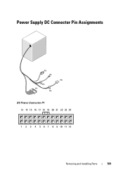
Power Supply DC Connector Pin Assignments DC Power Connector P1 13 14 15 16 17 18 19 20 21 22 23 24 1 2 3 4 5 6 7 8 9 10 11 12 Removing and Installing Parts 109
Power Supply DC Connector Pin Assignments DC Power Connector P1 13 14 15 16 17 18 19 20 21 22 23 24 1 2 3 4 5 6 7 8 9 10 11 12 Removing and Installing Parts 109
Owner's Manual
Page 110
Pin Number 1 2 3 4 5 6 7 8 9 10 11 12 13 14 15 16 17 18 19 20 21 22 23 24 Signal name 3.3 V 3.3 V RTN 5 V RTN 5 V RTN POK 5 V AUX +12 V +12 V 3.3 V 3.3 V -12 V RTN PS_ON RTN RTN RTN OPEN 5 V 5 V 5 V RTN Wire Color Orange Orange Black Red Black Red Black Gray Purple Yellow Yellow Orange Orange Blue Black Green Black Black Black Wire Size 20 AWG 20 AWG 20 AWG 20 AWG 20 AWG 20 AWG 20 AWG 22 AWG 20 AWG 20 AWG 20 AWG 20 AWG 20 AWG 22 AWG 20 AWG 22 AWG 20 AWG 20 AWG 20 AWG Red Red Red Black 20 AWG 20 AWG 20 AWG 20 AWG 110 Removing and Installing Parts
Pin Number 1 2 3 4 5 6 7 8 9 10 11 12 13 14 15 16 17 18 19 20 21 22 23 24 Signal name 3.3 V 3.3 V RTN 5 V RTN 5 V RTN POK 5 V AUX +12 V +12 V 3.3 V 3.3 V -12 V RTN PS_ON RTN RTN RTN OPEN 5 V 5 V 5 V RTN Wire Color Orange Orange Black Red Black Red Black Gray Purple Yellow Yellow Orange Orange Blue Black Green Black Black Black Wire Size 20 AWG 20 AWG 20 AWG 20 AWG 20 AWG 20 AWG 20 AWG 22 AWG 20 AWG 20 AWG 20 AWG 20 AWG 20 AWG 22 AWG 20 AWG 22 AWG 20 AWG 20 AWG 20 AWG Red Red Red Black 20 AWG 20 AWG 20 AWG 20 AWG 110 Removing and Installing Parts
Owner's Manual
Page 111
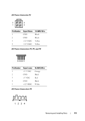
DC Power Connector P2 3 4 1 2 Pin Number 1 2 3 4 Signal Name GND GND +12 VADC +12 VADC 18-AWG Wire Black Black Yellow Yellow DC Power Connectors P3, P5, and P6 Pin Number 1 2 3 4 5 Signal name +3.3 VDC GND +5 VDC GND +12 VBDC 18-AWG Wire Orange Black Red Black White DC Power Connectors P4 Removing and Installing Parts 111
DC Power Connector P2 3 4 1 2 Pin Number 1 2 3 4 Signal Name GND GND +12 VADC +12 VADC 18-AWG Wire Black Black Yellow Yellow DC Power Connectors P3, P5, and P6 Pin Number 1 2 3 4 5 Signal name +3.3 VDC GND +5 VDC GND +12 VBDC 18-AWG Wire Orange Black Red Black White DC Power Connectors P4 Removing and Installing Parts 111
Owner's Manual
Page 112
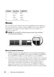
... modules on the type of DDR2 667-MHz and DDR2 800-MHz memory, the modules function at the slowest speed installed. 112 Removing and Installing Parts If a single DIMM is supported. Your computer supports DDR2 memory. Memory Installation Guidelines • DIMM connectors must install it in connector DIMM_1. • For best...
... modules on the type of DDR2 667-MHz and DDR2 800-MHz memory, the modules function at the slowest speed installed. 112 Removing and Installing Parts If a single DIMM is supported. Your computer supports DDR2 memory. Memory Installation Guidelines • DIMM connectors must install it in connector DIMM_1. • For best...

Owner's Manual
Page 113
... the Product Information Guide. NOTICE: To prevent static damage to components inside your computer, discharge static electricity from Dell is covered under your computer warranty. You should install your computer's electronic components. CAUTION: Before installing memory, you purchased ...the new modules from Dell. Removing and Installing Parts 113 You can do not pair an original memory module with a new memory module. 2 1 1 Pair A: matched ...
... the Product Information Guide. NOTICE: To prevent static damage to components inside your computer, discharge static electricity from Dell is covered under your computer warranty. You should install your computer's electronic components. CAUTION: Before installing memory, you purchased ...the new modules from Dell. Removing and Installing Parts 113 You can do not pair an original memory module with a new memory module. 2 1 1 Pair A: matched ...

Owner's Manual
Page 114
1 Follow the procedures in "Before You Begin" on page 101. 2 Press the securing clip at each end of the memory module connector. 1 2 3 1 memory connector farthest 2 securing clips (2) from processor (DIMM_2) 3 connector 3 Align the notch on the bottom of the module with the crossbar in the connector. 3 2 1 1 cutouts (2) 3 notch 4 2 memory module 4 crossbar 114 Removing and Installing Parts
1 Follow the procedures in "Before You Begin" on page 101. 2 Press the securing clip at each end of the memory module connector. 1 2 3 1 memory connector farthest 2 securing clips (2) from processor (DIMM_2) 3 connector 3 Align the notch on the bottom of the module with the crossbar in the connector. 3 2 1 1 cutouts (2) 3 notch 4 2 memory module 4 crossbar 114 Removing and Installing Parts

Owner's Manual
Page 115
... from your body before you touch any of the module. 4 Insert the module into the connector until the module snaps into position. Removing and Installing Parts 115 Removing Memory CAUTION: Before you begin any of your computer and devices to each end of memory (RAM) listed. If you insert the module...
... from your body before you touch any of the module. 4 Insert the module into the connector until the module snaps into position. Removing and Installing Parts 115 Removing Memory CAUTION: Before you begin any of your computer and devices to each end of memory (RAM) listed. If you insert the module...

Owner's Manual
Page 116
...replacing a card, remove the current driver for card slot location. You can do so by touching an unpainted metal surface on the computer chassis.Your Dell™ computer provides the following slots for PCI and PCI Express cards: • One PCI Express x16 card slot (SLOT1) • One ... See "System Board Components" on page 107 for the card from your computer, discharge static electricity from the operating system. 116 Removing and Installing Parts PCI and PCI Express Cards Your computer supports two PCI cards, one PCI Express x16 card and one PCI Express x1 card. • If ...
...replacing a card, remove the current driver for card slot location. You can do so by touching an unpainted metal surface on the computer chassis.Your Dell™ computer provides the following slots for PCI and PCI Express cards: • One PCI Express x16 card slot (SLOT1) • One ... See "System Board Components" on page 107 for the card from your computer, discharge static electricity from the operating system. 116 Removing and Installing Parts PCI and PCI Express Cards Your computer supports two PCI cards, one PCI Express x16 card and one PCI Express x1 card. • If ...
Owner's Manual
Page 117
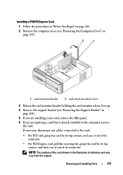
... filler panel. 6 If you are replacing a card that is indicative and may vary from the original. NOTE: The position of its connector. Removing and Installing Parts 117
... filler panel. 6 If you are replacing a card that is indicative and may vary from the original. NOTE: The position of its connector. Removing and Installing Parts 117
Owner's Manual
Page 118
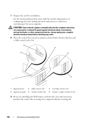
... shock, laceration by moving fan blades, or other unexpected injuries, always unplug your computer. Ensure that came with the securing tab. 118 Removing and Installing Parts CAUTION: Some network adapters automatically start the computer when they are installing the PCI Express card into the x16 card connector, position the card so...
... shock, laceration by moving fan blades, or other unexpected injuries, always unplug your computer. Ensure that came with the securing tab. 118 Removing and Installing Parts CAUTION: Some network adapters automatically start the computer when they are installing the PCI Express card into the x16 card connector, position the card so...
Owner's Manual
Page 119
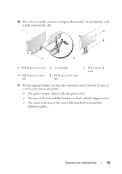
... x1 card slot 5 PCI Express x16 card slot 3 PCI Express x1 card 11 Fix the support bracket and then press down firmly. Removing and Installing Parts 119
... x1 card slot 5 PCI Express x16 card slot 3 PCI Express x1 card 11 Fix the support bracket and then press down firmly. Removing and Installing Parts 119

