Service Manual
Page 4
Replacing the Module Cover 22 6 Memory Module(s 23 Removing the Memory Module(s 23 Replacing the Memory Module(s 24 7 Keyboard 27 Removing the Keyboard 27 Replacing the Keyboard 29 8 Palm-Rest Assembly 31 Removing the Palm-Rest Assembly 31 Replacing the Palm-Rest Assembly 35 9 Hot-Key Board 37 Removing the Hot-Key Board 37 Replacing the Hot-Key Board 38 10 Power-Button Board 41 Removing the Power-Button Board 41 Replacing the Power-Button Board 42 4 Contents
Replacing the Module Cover 22 6 Memory Module(s 23 Removing the Memory Module(s 23 Replacing the Memory Module(s 24 7 Keyboard 27 Removing the Keyboard 27 Replacing the Keyboard 29 8 Palm-Rest Assembly 31 Removing the Palm-Rest Assembly 31 Replacing the Palm-Rest Assembly 35 9 Hot-Key Board 37 Removing the Hot-Key Board 37 Replacing the Hot-Key Board 38 10 Power-Button Board 41 Removing the Power-Button Board 41 Replacing the Power-Button Board 42 4 Contents

Service Manual
Page 6
Replacing the Thermal Fan 66 16 System Board 69 Removing the System Board 69 Replacing the System Board 72 Entering the Service Tag in the BIOS 73 17 Coin-Cell Battery 75 Removing the Coin-Cell Battery 75 Replacing the Coin-Cell Battery 76 18 I/O Board 79 Removing the I/O Board 79 Replacing the I/O Board 80 19 Thermal Cooling Assembly 81 Removing the Thermal Cooling Assembly 81 Replacing the Thermal Cooling Assembly 82 20 Processor Module 85 Removing the Processor Module 85 Replacing the Processor Module 86 6 Contents
Replacing the Thermal Fan 66 16 System Board 69 Removing the System Board 69 Replacing the System Board 72 Entering the Service Tag in the BIOS 73 17 Coin-Cell Battery 75 Removing the Coin-Cell Battery 75 Replacing the Coin-Cell Battery 76 18 I/O Board 79 Removing the I/O Board 79 Replacing the I/O Board 80 19 Thermal Cooling Assembly 81 Removing the Thermal Cooling Assembly 81 Replacing the Thermal Cooling Assembly 82 20 Processor Module 85 Removing the Processor Module 85 Replacing the Processor Module 86 6 Contents

Service Manual
Page 7
... Display Assembly 89 Replacing the Display Assembly 91 Display Bezel 92 Removing the Display Bezel 92 Replacing the Display Bezel 93 Removing the Display Panel 94 Replacing the Display Panel 94 Replacing the Display Cable 96 Removing the Display Hinges 97 Replacing the Display Hinges 98 Removing the Display-Panel Brackets 98 Replacing the Display-Panel Brackets 99 22 Camera Module 101 Removing the Camera Module 101 Replacing the Camera Module 102 23 Hinge Cover 105 Removing the Hinge Cover 105 Replacing the Hinge Cover 108 24 AC-Adapter Connector 111 Removing...
... Display Assembly 89 Replacing the Display Assembly 91 Display Bezel 92 Removing the Display Bezel 92 Replacing the Display Bezel 93 Removing the Display Panel 94 Replacing the Display Panel 94 Replacing the Display Cable 96 Removing the Display Hinges 97 Replacing the Display Hinges 98 Removing the Display-Panel Brackets 98 Replacing the Display-Panel Brackets 99 22 Camera Module 101 Removing the Camera Module 101 Replacing the Camera Module 102 23 Hinge Cover 105 Removing the Hinge Cover 105 Replacing the Hinge Cover 108 24 AC-Adapter Connector 111 Removing...
Service Manual
Page 10
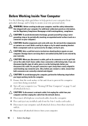
... and clean to prevent the computer cover from being scratched. 2 Turn off your computer (see the Regulatory Compliance Homepage at dell.com/regulatory_compliance. WARNING: Before working inside your computer, read the safety information that both connectors are disconnecting this type of cable, press in -1 media card reader. 5 Disconnect your computer and all attached devices from their electrical outlets. 6 Disconnect all...
... and clean to prevent the computer cover from being scratched. 2 Turn off your computer (see the Regulatory Compliance Homepage at dell.com/regulatory_compliance. WARNING: Before working inside your computer, read the safety information that both connectors are disconnecting this type of cable, press in -1 media card reader. 5 Disconnect your computer and all attached devices from their electrical outlets. 6 Disconnect all...
Service Manual
Page 22
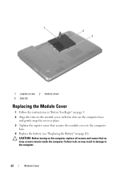
CAUTION: Before turning on the computer, replace all screws and ensure that secures the module cover to the computer base. 4 Replace the battery (see "Replacing the Battery" on the computer base and gently snap the cover in damage to the computer. 22 Module Cover 1 2 3 1 captive screw 2 module cover 3 tabs (3) Replacing the Module Cover 1 Follow the instructions in "Before You Begin" on page 9. 2 Align the tabs on the module cover with the slots on page 16). Failure to do so may result in place. 3 Tighten the captive screw that no stray screws remain inside the computer.
CAUTION: Before turning on the computer, replace all screws and ensure that secures the module cover to the computer base. 4 Replace the battery (see "Replacing the Battery" on the computer base and gently snap the cover in damage to the computer. 22 Module Cover 1 2 3 1 captive screw 2 module cover 3 tabs (3) Replacing the Module Cover 1 Follow the instructions in "Before You Begin" on page 9. 2 Align the tabs on the module cover with the slots on page 16). Failure to do so may result in place. 3 Tighten the captive screw that no stray screws remain inside the computer.
Service Manual
Page 23
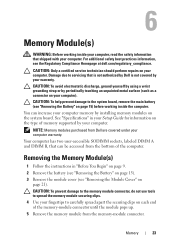
.... Your computer has two user-accessible SODIMM sockets, labeled DIMM A and DIMM B, that is not authorized by Dell is not covered by your computer. CAUTION: To help prevent damage to spread the memory module securing clips. 4 Use your computer). CAUTION: Only a certified service technician should perform repairs on the system board. Removing the Memory Module(s) 1 Follow the instructions in your Setup Guide for information on your...
.... Your computer has two user-accessible SODIMM sockets, labeled DIMM A and DIMM B, that is not authorized by Dell is not covered by your computer. CAUTION: To help prevent damage to spread the memory module securing clips. 4 Use your computer). CAUTION: Only a certified service technician should perform repairs on the system board. Removing the Memory Module(s) 1 Follow the instructions in your Setup Guide for information on your...

Service Manual
Page 24
NOTE: If the memory module is not installed properly, the computer may not boot. 24 Memory 1 3 2 1 memory-module connector 2 securing clips (2) 3 memory module Replacing the Memory Module(s) CAUTION: If you need to install memory modules in two connectors, install a memory module in the memory-module connector. 3 Slide the memory module firmly into the slot at a 45-degree angle, and press the memory module down until it . If you install a memory module in the connector labeled "DIMM B." 1 Follow the instructions in "Before...
NOTE: If the memory module is not installed properly, the computer may not boot. 24 Memory 1 3 2 1 memory-module connector 2 securing clips (2) 3 memory module Replacing the Memory Module(s) CAUTION: If you need to install memory modules in two connectors, install a memory module in the memory-module connector. 3 Slide the memory module firmly into the slot at a 45-degree angle, and press the memory module down until it . If you install a memory module in the connector labeled "DIMM B." 1 Follow the instructions in "Before...
Service Manual
Page 48
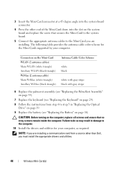
... step 5 in "Replacing the Optical Drive" on page 19. 9 Replace the battery (see "Replacing the Keyboard" on page 29). 8 Follow the instructions from a source other end of the Mini-Card down into the system-board connector. 4 Press the other than Dell, you are installing. 3 Insert the Mini-Card connector at a 45-degree angle into the slot on the system board and replace the screw that...
... step 5 in "Replacing the Optical Drive" on page 19. 9 Replace the battery (see "Replacing the Keyboard" on page 29). 8 Follow the instructions from a source other end of the Mini-Card down into the system-board connector. 4 Press the other than Dell, you are installing. 3 Insert the Mini-Card connector at a 45-degree angle into the slot on the system board and replace the screw that...
Service Manual
Page 49
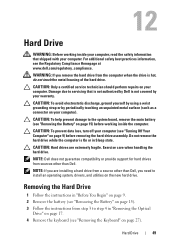
... operating system, drivers, and utilities on the new hard drive. CAUTION: To prevent data loss, turn off your computer (see the Regulatory Compliance Homepage at www.dell.com/regulatory_compliance. Damage due to the system board, remove the main battery (see "Removing the Keyboard" on page 27). 12 Hard Drive WARNING: Before working inside your computer, read the safety information that is not authorized by Dell is not covered...
... operating system, drivers, and utilities on the new hard drive. CAUTION: To prevent data loss, turn off your computer (see the Regulatory Compliance Homepage at www.dell.com/regulatory_compliance. Damage due to the system board, remove the main battery (see "Removing the Keyboard" on page 27). 12 Hard Drive WARNING: Before working inside your computer, read the safety information that is not authorized by Dell is not covered...
Service Manual
Page 51
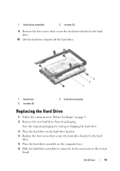
... the system board. 1 hard-drive assembly 2 screws (3) 9 Remove the four screws that secure the hard-drive bracket to the hard drive. 10 Lift the hard-drive bracket off the hard drive. 3 2 1 1 hard drive 3 screws (4) 2 hard-drive bracket Replacing the Hard Drive 1 Follow the instructions in the hard-drive bracket. 4 Replace the four screws that secure the hard-drive bracket to the hard drive. 5 Place the hard-drive assembly on the computer base. 6 Slide the hard-drive assembly to connect it to the...
... the system board. 1 hard-drive assembly 2 screws (3) 9 Remove the four screws that secure the hard-drive bracket to the hard drive. 10 Lift the hard-drive bracket off the hard drive. 3 2 1 1 hard drive 3 screws (4) 2 hard-drive bracket Replacing the Hard Drive 1 Follow the instructions in the hard-drive bracket. 4 Replace the four screws that secure the hard-drive bracket to the hard drive. 5 Place the hard-drive assembly on the computer base. 6 Slide the hard-drive assembly to connect it to the...
Service Manual
Page 72
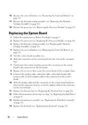
... display cable to the connector on the system board. 11 Replace the thermal fan (see "Replacing the Thermal Fan" on page 66). 12 Follow the instructions from step 5 to step 7 in "Replacing the Hard Drive" on page 51. 13 Replace the palm-rest assembly (see "Replacing the Palm-Rest Assembly" on page 35). 14 Replace the keyboard (see "Removing the Processor Module" on page 29). 72 System Board...
... display cable to the connector on the system board. 11 Replace the thermal fan (see "Replacing the Thermal Fan" on page 66). 12 Follow the instructions from step 5 to step 7 in "Replacing the Hard Drive" on page 51. 13 Replace the palm-rest assembly (see "Replacing the Palm-Rest Assembly" on page 35). 14 Replace the keyboard (see "Removing the Processor Module" on page 29). 72 System Board...
Service Manual
Page 73
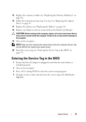
... you removed from step 4 to step 5 in "Replacing the Optical Drive" on page 19. 17 Replace the battery (see "Replacing the Battery" on page 16). 18 Replace any blank or card you have replaced the system board, enter the computer Service Tag into the BIOS of the replacement system board. 20 Enter the service tag (see "Replacing the Memory Module(s)" on page 24). 16 Follow the instructions from the Media Card Reader. CAUTION: Before turning on...
... you removed from step 4 to step 5 in "Replacing the Optical Drive" on page 19. 17 Replace the battery (see "Replacing the Battery" on page 16). 18 Replace any blank or card you have replaced the system board, enter the computer Service Tag into the BIOS of the replacement system board. 20 Enter the service tag (see "Replacing the Memory Module(s)" on page 24). 16 Follow the instructions from the Media Card Reader. CAUTION: Before turning on...

Setup Guide
Page 5
... Inspiron Laptop 5 Before Setting Up Your Computer 5 Connect the AC Adapter 6 Connect the Network Cable (Optional 7 Press the Power Button 8 Set Up the Operating System 9 Create System Recovery Media (Recommended 10 Enable or Disable Wireless (Optional 12 Set Up Wireless Display (Optional 14 Connect to the Internet (Optional 16 Using Your Inspiron Laptop 18 Right View Features 18 Left View Features 20 Back View Features 24 Front View Features 26 Status Lights and Indicators 28 Disabling Battery Charging 30 Computer Base and Keyboard Features 32 Touch Pad...
... Inspiron Laptop 5 Before Setting Up Your Computer 5 Connect the AC Adapter 6 Connect the Network Cable (Optional 7 Press the Power Button 8 Set Up the Operating System 9 Create System Recovery Media (Recommended 10 Enable or Disable Wireless (Optional 12 Set Up Wireless Display (Optional 14 Connect to the Internet (Optional 16 Using Your Inspiron Laptop 18 Right View Features 18 Left View Features 20 Back View Features 24 Front View Features 26 Status Lights and Indicators 28 Disabling Battery Charging 30 Computer Base and Keyboard Features 32 Touch Pad...

Setup Guide
Page 6
... Problems 54 Beep Codes 54 Network Problems 55 Power Problems 55 Memory Problems 57 Lockups and Software Problems 57 Using Support Tools 60 Dell Support Center 60 My Dell Downloads 61 Hardware Troubleshooter 62 Dell Diagnostics 62 Restoring Your Operating System 64 System Restore 65 Dell DataSafe Local Backup 66 System Recovery Media 69 Dell Factory Image Restore 70 Getting Help 72 Technical Support and Customer Service 73 DellConnect 73 Online Services 74 Automated Order-Status Service 75 Product Information 75 Returning Items for Repair...
... Problems 54 Beep Codes 54 Network Problems 55 Power Problems 55 Memory Problems 57 Lockups and Software Problems 57 Using Support Tools 60 Dell Support Center 60 My Dell Downloads 61 Hardware Troubleshooter 62 Dell Diagnostics 62 Restoring Your Operating System 64 System Restore 65 Dell DataSafe Local Backup 66 System Recovery Media 69 Dell Factory Image Restore 70 Getting Help 72 Technical Support and Customer Service 73 DellConnect 73 Online Services 74 Automated Order-Status Service 75 Product Information 75 Returning Items for Repair...

Setup Guide
Page 17
.... 5. The Intel Wireless Display window appears. 2. Select your computer. 2. Enter the security code that appears on the keyboard to enable wireless. 3. Press along with the < > on the function key row on your TV, such as HDMI1, HDMI2, or S-Video. 6. Select Scan for available displays. 8. Click the Intel Wireless Display icon on your wireless display adapter from support.dell.com. Connect the wireless display adapter to Existing Adapter. Setting Up Your Inspiron Laptop To set up wireless display: 1. Turn on the desktop.
.... 5. The Intel Wireless Display window appears. 2. Select your computer. 2. Enter the security code that appears on the keyboard to enable wireless. 3. Press along with the < > on the function key row on your TV, such as HDMI1, HDMI2, or S-Video. 6. Select Scan for available displays. 8. Click the Intel Wireless Display icon on your wireless display adapter from support.dell.com. Connect the wireless display adapter to Existing Adapter. Setting Up Your Inspiron Laptop To set up wireless display: 1. Turn on the desktop.
Setup Guide
Page 35
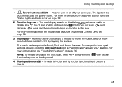
... computer. NOTE: To enable or disable the touch pad, press along with the < > key on the function key row on a mouse. 33 Using Your Inspiron Laptop 1 Power button and light - For more information, see "Status Lights and Indicators" on page 38. 3 Touch pad - Press to move the cursor, drag or move selected items, and left -click and right-click functions like those on the keyboard. 4 Touch pad buttons (2) - The touch pad supports the Scroll, Flick, and Zoom...
... computer. NOTE: To enable or disable the touch pad, press along with the < > key on the function key row on a mouse. 33 Using Your Inspiron Laptop 1 Power button and light - For more information, see "Status Lights and Indicators" on page 38. 3 Touch pad - Press to move the cursor, drag or move selected items, and left -click and right-click functions like those on the keyboard. 4 Touch pad buttons (2) - The touch pad supports the Scroll, Flick, and Zoom...
Setup Guide
Page 58
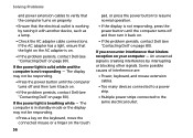
.... • Press a key on the keyboard, move the connected mouse or a finger on the touch 56 pad, or press the power button to resume normal operation. • If the display is not responding, press the power button until the computer turns off and then turn it back on. • If the problem persists, contact Dell (see "Contacting Dell" on page 80). Solving Problems and power extension cables to verify that...
.... • Press a key on the keyboard, move the connected mouse or a finger on the touch 56 pad, or press the power button to resume normal operation. • If the display is not responding, press the power button until the computer turns off and then turn it back on. • If the problem persists, contact Dell (see "Contacting Dell" on page 80). Solving Problems and power extension cables to verify that...

Setup Guide
Page 59
... Task. 57 If necessary, install additional memory (see the Service Manual at support.dell.com/manuals). • Reseat the memory module(s) into the connector(s) (see the Service Manual at support.dell.com/manuals). • If the problem persists, contact Dell (see "Contacting Dell" on page 80). Ensure that the AC adapter cable is no longer responding 4. Lockups and Software Problems If the computer does not start up - Solving Problems Memory Problems If you receive an...
... Task. 57 If necessary, install additional memory (see the Service Manual at support.dell.com/manuals). • Reseat the memory module(s) into the connector(s) (see the Service Manual at support.dell.com/manuals). • If the problem persists, contact Dell (see "Contacting Dell" on page 80). Ensure that the AC adapter cable is no longer responding 4. Lockups and Software Problems If the computer does not start up - Solving Problems Memory Problems If you receive an...

Setup Guide
Page 86
NOTE: Offerings may need when setting up, updating drivers for, and upgrading your computer. Computer Model Memory Dell Inspiron N7110 Computer Information System chipset Mobile Intel 6 series Processor types Intel Core i3 Intel Core i5 Intel Core i7 Intel Pentium Dual Core Memory module connector Memory module capacities Minimum memory Maximum memory two user-accessible SODIMM connectors 1 GB, 2 GB, and 4 GB 2 GB 8 GB Possible memory 2 GB, 3 GB, 4 GB, 6 GB, configurations and 8 GB 84...
NOTE: Offerings may need when setting up, updating drivers for, and upgrading your computer. Computer Model Memory Dell Inspiron N7110 Computer Information System chipset Mobile Intel 6 series Processor types Intel Core i3 Intel Core i5 Intel Core i7 Intel Pentium Dual Core Memory module connector Memory module capacities Minimum memory Maximum memory two user-accessible SODIMM connectors 1 GB, 2 GB, and 4 GB 2 GB 8 GB Possible memory 2 GB, 3 GB, 4 GB, 6 GB, configurations and 8 GB 84...

Setup Guide
Page 96
Index products information and purchasing 75 R resources, finding more 82 restoring factory image 70 S Service Tag locating 78 setup, before you begin 5 shipping products for return or repair 76 software features 50 software problems 57 solving problems 54 specifications 84 support e-mail addresses 74 support sites 94 worldwide 73 System Recovery Media 69 system reinstall options 64 System Restore 65 T Touch Pad Gestures 36 U Using the Emergency Eject Hole 40 V ventilation, ensuring 5 W warranty returns 76 Windows Program Compatibility Wizard 58 Windows Mobility Center 38
Index products information and purchasing 75 R resources, finding more 82 restoring factory image 70 S Service Tag locating 78 setup, before you begin 5 shipping products for return or repair 76 software features 50 software problems 57 solving problems 54 specifications 84 support e-mail addresses 74 support sites 94 worldwide 73 System Recovery Media 69 system reinstall options 64 System Restore 65 T Touch Pad Gestures 36 U Using the Emergency Eject Hole 40 V ventilation, ensuring 5 W warranty returns 76 Windows Program Compatibility Wizard 58 Windows Mobility Center 38


