Service Manual
Page 1
Dell™ Inspiron™ 1764 Service Manual Before You Begin Battery Optical Drive Module Cover Coin-Cell Battery Memory Module(s) Wireless Mini-Card Hard Drive Power Button Panel Keyboard Palm ... Technology Processor Fan USB/Audio Board Optical Drive Board Microphone AC Adapter Connector Speakers System Board Processor Heat Sink Processor Module USB Connector Battery Latch Assembly Display Camera Module Flashing the BIOS Notes, Cautions, and Warnings NOTE: A NOTE indicates important information that helps you how to avoid the problem. WARNING: A WARNING indicates...
Dell™ Inspiron™ 1764 Service Manual Before You Begin Battery Optical Drive Module Cover Coin-Cell Battery Memory Module(s) Wireless Mini-Card Hard Drive Power Button Panel Keyboard Palm ... Technology Processor Fan USB/Audio Board Optical Drive Board Microphone AC Adapter Connector Speakers System Board Processor Heat Sink Processor Module USB Connector Battery Latch Assembly Display Camera Module Flashing the BIOS Notes, Cautions, and Warnings NOTE: A NOTE indicates important information that helps you how to avoid the problem. WARNING: A WARNING indicates...
Service Manual
Page 10
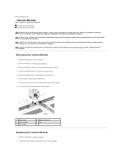
... the camera cable to the connector on your computer. Remove the battery (see Removing the Display Assembly). 4. Remove the display assembly (see Removing the Battery). 3. Remove the display bezel (see Removing the Battery) before working inside the computer. Disconnect the camera cable from...To help prevent damage to the system board, remove the main battery (see Removing the Display Bezel). 5. Back to Contents Page Camera Module Dell™ Inspiron™ 1764 Service Manual Removing the Camera Module Replacing the Camera Module WARNING: Before working inside your computer...
... the camera cable to the connector on your computer. Remove the battery (see Removing the Display Assembly). 4. Remove the display assembly (see Removing the Battery). 3. Remove the display bezel (see Removing the Battery) before working inside the computer. Disconnect the camera cable from...To help prevent damage to the system board, remove the main battery (see Removing the Display Bezel). 5. Back to Contents Page Camera Module Dell™ Inspiron™ 1764 Service Manual Removing the Camera Module Replacing the Camera Module WARNING: Before working inside your computer...

Service Manual
Page 11
... to the camera module. 4. Replace the battery (see Replacing the Display Assembly). 9. Replace the tape to secure the camera cable to the display cover. 6. Replace the display assembly (see Replacing the Battery). Use the alignment posts to the computer. Replace the display bezel (see Replacing the Display Panel). 7. Failure to do so may result in damage to...
... to the camera module. 4. Replace the battery (see Replacing the Display Assembly). 9. Replace the tape to secure the camera cable to the display cover. 6. Replace the display assembly (see Replacing the Battery). Use the alignment posts to the computer. Replace the display bezel (see Replacing the Display Panel). 7. Failure to do so may result in damage to...
Service Manual
Page 19
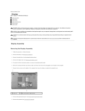
... computer. Remove the power button panel (see Removing the Battery). 3. Back to Contents Page Display Dell™ Inspiron™ 1764 Service Manual Display Assembly Display Bezel Display Panel Display Panel Brackets Display Hinges Display Cable WARNING: Before working inside your computer, read the safety information that secure the display assembly to the computer base. 1 screws (2) 2 Mini-Card antenna cable routing 8. Remove the battery...
... computer. Remove the power button panel (see Removing the Battery). 3. Back to Contents Page Display Dell™ Inspiron™ 1764 Service Manual Display Assembly Display Bezel Display Panel Display Panel Brackets Display Hinges Display Cable WARNING: Before working inside your computer, read the safety information that secure the display assembly to the computer base. 1 screws (2) 2 Mini-Card antenna cable routing 8. Remove the battery...

Service Manual
Page 20
... from the routing guides on the palm rest. 12. Lift the display assembly off the alignment posts on the computer base. Pull the Mini-Card antenna cables up through the slot in Before You ...the system board, and remove the display cable grounding screw. 1 Mini-Card antenna cable routing 3 display cable 2 display cable grounding screw 4 slot in place and remove the three screws that secure the display assembly to place the display assembly on the computer base. 1 display assembly 3 display hinges (2) 2 screws (3) Replacing the Display Assembly 1. Follow the procedures in the computer...
... from the routing guides on the palm rest. 12. Lift the display assembly off the alignment posts on the computer base. Pull the Mini-Card antenna cables up through the slot in Before You ...the system board, and remove the display cable grounding screw. 1 Mini-Card antenna cable routing 3 display cable 2 display cable grounding screw 4 slot in place and remove the three screws that secure the display assembly to place the display assembly on the computer base. 1 display assembly 3 display hinges (2) 2 screws (3) Replacing the Display Assembly 1. Follow the procedures in the computer...

Service Manual
Page 21
... antenna cables (see Removing the Display Assembly). 3. Follow the procedures in the computer base. 7. Display Bezel Removing the Display Bezel CAUTION: The display bezel is extremely fragile. Be careful when removing it from the display assembly. 1 display bezel 2 display assembly Replacing the Display Bezel 1. Carefully pull up around... the Mini-Card antenna cables through the notch on the computer, replace all screws and ensure that secure the display assembly to the computer. Replace the keyboard (see Replacing the Power Button Panel). 11. Replace the module cover (see...
... antenna cables (see Removing the Display Assembly). 3. Follow the procedures in the computer base. 7. Display Bezel Removing the Display Bezel CAUTION: The display bezel is extremely fragile. Be careful when removing it from the display assembly. 1 display bezel 2 display assembly Replacing the Display Bezel 1. Carefully pull up around... the Mini-Card antenna cables through the notch on the computer, replace all screws and ensure that secure the display assembly to the computer. Replace the keyboard (see Replacing the Power Button Panel). 11. Replace the module cover (see...

Service Manual
Page 22
... do so may result in Before You Begin. 2. Replace the display assembly (see Removing the Display Assembly). 3. Failure to the computer. Remove the display bezel (see Replacing the Battery). Replace the battery (see Removing the Display Bezel). 4. Display Panel Removing the Display Panel 1. CAUTION: Before turning on the display panel. Remove the six screws that no stray screws remain...
... do so may result in Before You Begin. 2. Replace the display assembly (see Removing the Display Assembly). 3. Failure to the computer. Remove the display bezel (see Replacing the Battery). Replace the battery (see Removing the Display Bezel). 4. Display Panel Removing the Display Panel 1. CAUTION: Before turning on the display panel. Remove the six screws that no stray screws remain...

Service Manual
Page 23
... brackets to the connector on the display cover. 4. Replace the display assembly (see Replacing the Display Bezel). 6. Failure to do so may result in damage to the display cover. 5. Remove the display panel (see Removing the Display Bezel). 4. Connect the display cable to the display panel. 1 display panel brackets (2) 3 display panel 2 screws (6) Replacing the Display Panel Brackets Remove the six screws that...
... brackets to the connector on the display cover. 4. Replace the display assembly (see Replacing the Display Bezel). 6. Failure to do so may result in damage to the display cover. 5. Remove the display panel (see Removing the Display Bezel). 4. Connect the display cable to the display panel. 1 display panel brackets (2) 3 display panel 2 screws (6) Replacing the Display Panel Brackets Remove the six screws that...

Service Manual
Page 24
... the four screws that secure the display panel brackets to the display panel. 3. Replace the display assembly (see Replacing the Display Panel). 4. 1. Replace the display panel (see Replacing the Display Assembly). Remove the display panel (see Replacing the Display Panel). 5. Replace the display panel (see Removing the Display Panel). 5. Replace the six screws that secure the display hinges to the computer. Follow the...
... the four screws that secure the display panel brackets to the display panel. 3. Replace the display assembly (see Replacing the Display Panel). 4. 1. Replace the display panel (see Replacing the Display Assembly). Remove the display panel (see Replacing the Display Panel). 5. Replace the display panel (see Removing the Display Panel). 5. Replace the six screws that secure the display hinges to the computer. Follow the...

Service Manual
Page 25
... in Before You Begin. 2. Remove the display assembly (see Replacing the Display Assembly). 7. Replacing the Display Cable 1. Replace the display assembly (see Removing the Display Assembly). 3. Failure to do so may result in damage to the computer. Remove the display panel (see Replacing the Display Panel). 5. Replace the display panel (see Removing the Display Panel). 5. Replace the display bezel (see Replacing the Battery). CAUTION...
... in Before You Begin. 2. Remove the display assembly (see Replacing the Display Assembly). 7. Replacing the Display Cable 1. Replace the display assembly (see Removing the Display Assembly). 3. Failure to do so may result in damage to the computer. Remove the display panel (see Replacing the Display Panel). 5. Replace the display panel (see Removing the Display Panel). 5. Replace the display bezel (see Replacing the Battery). CAUTION...


