
Owner's Manual
Page 10
...Memory Module 150 Replacing the DIMM A Memory Module . . . . . 152 Removing the DIMM B Memory Module 153 Replacing the DIMM B Memory Module . . . . . 154 Subscriber Identity Module 156 Wireless Mini Cards 157 Removing a WLAN Card 157 Replacing a WLAN Card 159 Removing a Mobile Broadband or WWAN Card . . 160 Replacing a WWAN Card 163 Removing a WPAN Card 164 Replacing... Technology . 165 Removing the Card 165 Replacing the Card 166 Coin-Cell Battery 166 Removing the Coin-Cell Battery 167 Replacing the Coin-Cell Battery 167 14 Dell™ QuickSet Features 169 15 Traveling With...
...Memory Module 150 Replacing the DIMM A Memory Module . . . . . 152 Removing the DIMM B Memory Module 153 Replacing the DIMM B Memory Module . . . . . 154 Subscriber Identity Module 156 Wireless Mini Cards 157 Removing a WLAN Card 157 Replacing a WLAN Card 159 Removing a Mobile Broadband or WWAN Card . . 160 Replacing a WWAN Card 163 Removing a WPAN Card 164 Replacing... Technology . 165 Removing the Card 165 Replacing the Card 166 Coin-Cell Battery 166 Removing the Coin-Cell Battery 167 Replacing the Coin-Cell Battery 167 14 Dell™ QuickSet Features 169 15 Traveling With...

Owner's Manual
Page 31
... the volume control buttons or the mute button. Stores software and data. Compartment that allows certain software applications to an electrical outlet (see "Adding and Replacing Parts" on page 47). B A T T E R Y C H A R G E / H E A L T H G A U G E - R I C A R D C O M P A R T M E N T - To adjust the volume of...use the computer without connecting the computer to be controlled by the Dell Travel Remote. 1 left speaker 3 consumer IR 5 wireless mini card compartment 7 battery charge/health gauge 9 fan 2 memory module/coin-cell battery compartment 4 right speaker 6 battery 8 ...
... the volume control buttons or the mute button. Stores software and data. Compartment that allows certain software applications to an electrical outlet (see "Adding and Replacing Parts" on page 47). B A T T E R Y C H A R G E / H E A L T H G A U G E - R I C A R D C O M P A R T M E N T - To adjust the volume of...use the computer without connecting the computer to be controlled by the Dell Travel Remote. 1 left speaker 3 consumer IR 5 wireless mini card compartment 7 battery charge/health gauge 9 fan 2 memory module/coin-cell battery compartment 4 right speaker 6 battery 8 ...

Owner's Manual
Page 113
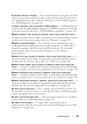
... may be faulty or improperly seated. Reinstall the memory modules and, if necessary, replace them (see "Memory" on page 143). The operation requires a hard drive in the hard drive bay (see "Dell Diagnostics" on page 150). Install a hard drive in the bay before it can continue. A memory module may be loose. H A R D - D I S K D R I V E C O N F I G U.... Restart the computer. Try copying the file to fit on page 101). Reinstall the memory modules and, if necessary, replace them (see "Using ExpressCards" on page 109). The operating system is full. DRIVE ...
... may be faulty or improperly seated. Reinstall the memory modules and, if necessary, replace them (see "Memory" on page 143). The operation requires a hard drive in the hard drive bay (see "Dell Diagnostics" on page 150). Install a hard drive in the bay before it can continue. A memory module may be loose. H A R D - D I S K D R I V E C O N F I G U.... Restart the computer. Try copying the file to fit on page 101). Reinstall the memory modules and, if necessary, replace them (see "Using ExpressCards" on page 109). The operating system is full. DRIVE ...
Owner's Manual
Page 115
... 150). The computer cannot find the hard drive. Run the Stuck Key test in the Dell Diagnostics (see "Memory" on page 101). Reinstall the memory modules and, if necessary, replace them (see "Memory" on page 150). Reinstall the memory modules and, if necessary, replace them (see "Memory" on page 150). A memory module may be played (see the software documentation.
... 150). The computer cannot find the hard drive. Run the Stuck Key test in the Dell Diagnostics (see "Memory" on page 101). Reinstall the memory modules and, if necessary, replace them (see "Memory" on page 150). Reinstall the memory modules and, if necessary, replace them (see "Memory" on page 150). A memory module may be played (see the software documentation.

Owner's Manual
Page 117
... Broadband (WWAN) ExpressCards, see "Contacting Dell" on page 101). Run the System Memory tests and the Keyboard Controller test in the system setup program does not match the system clock. Insert a disk into the connector. WA R N I N G : B A T T E R Y I S C R I T I D E D E X P R E S S C A R D - The battery is properly inserted into the drive and try again. Replace the battery, or connect the...
... Broadband (WWAN) ExpressCards, see "Contacting Dell" on page 101). Run the System Memory tests and the Keyboard Controller test in the system setup program does not match the system clock. Insert a disk into the connector. WA R N I N G : B A T T E R Y I S C R I T I D E D E X P R E S S C A R D - The battery is properly inserted into the drive and try again. Replace the battery, or connect the...

Owner's Manual
Page 123
...Dell Diagnostics (see "Dell Diagnostics" on page 101). IF YOU RECEIVE AN INSUFFICIENT MEMORY MESSAGE - • Save and close any open files and exit any open programs you begin any of the procedures in this section, follow the safety instructions in the Product Information Guide. Replace the network cable. If necessary, install additional memory (see "Memory..." on page 150). • Reseat the memory modules to see if that no network ...
...Dell Diagnostics (see "Dell Diagnostics" on page 101). IF YOU RECEIVE AN INSUFFICIENT MEMORY MESSAGE - • Save and close any open files and exit any open programs you begin any of the procedures in this section, follow the safety instructions in the Product Information Guide. Replace the network cable. If necessary, install additional memory (see "Memory..." on page 150). • Reseat the memory modules to see if that no network ...

Owner's Manual
Page 143
... the procedures in this section, follow the safety instructions in the Product Information Guide. NOTICE: To prevent data loss, turn off your computer (see "Removing a Memory Card or Blank" on page 85). Do not remove the hard drive while the computer is hot, do not touch the metal housing of the... display, and press the power button to ground the system board. 9 Remove any installed cards from the computer when the drive is on or in -1 memory card reader (see "Turning Off Your Computer" on page 81) and the 8-in Sleep state. Adding and...
... the procedures in this section, follow the safety instructions in the Product Information Guide. NOTICE: To prevent data loss, turn off your computer (see "Removing a Memory Card or Blank" on page 85). Do not remove the hard drive while the computer is hot, do not touch the metal housing of the... display, and press the power button to ground the system board. 9 Remove any installed cards from the computer when the drive is on or in -1 memory card reader (see "Turning Off Your Computer" on page 81) and the 8-in Sleep state. Adding and...

Owner's Manual
Page 149
Be careful when removing and handling the keyboard. 4 Lift the keyboard and hold it up and slightly forward to access to replace. NOTICE: The key caps on the keyboard are fragile, easily dislodged, and timeconsuming to the keyboard connector. 5 To disconnect the keyboard cable from the keyboard ... the keyboard. Removing the Keyboard 1 Follow the procedures in "Before You Begin" on page 141. 2 Remove the hinge cover (see "Hinge Cover" on the DIMM A memory module cover. 1 2 3 4 5 1 screws (2) 3 tabs (5) 5 cable release lever 2 keyboard 4 keyboard cable Adding and Replacing Parts 149
Be careful when removing and handling the keyboard. 4 Lift the keyboard and hold it up and slightly forward to access to replace. NOTICE: The key caps on the keyboard are fragile, easily dislodged, and timeconsuming to the keyboard connector. 5 To disconnect the keyboard cable from the keyboard ... the keyboard. Removing the Keyboard 1 Follow the procedures in "Before You Begin" on page 141. 2 Remove the hinge cover (see "Hinge Cover" on the DIMM A memory module cover. 1 2 3 4 5 1 screws (2) 3 tabs (5) 5 cable release lever 2 keyboard 4 keyboard cable Adding and Replacing Parts 149

Owner's Manual
Page 150
... and Replacing Parts See "Specifications" on page 181 for your computer memory by installing memory modules on the memory supported by periodically touching an unpainted metal surface (such as a connector on the back of the keyboard. NOTICE: If your computer has only one accessed from beneath the keyboard (DIMM A), and the other accessed from Dell...
... and Replacing Parts See "Specifications" on page 181 for your computer memory by installing memory modules on the memory supported by periodically touching an unpainted metal surface (such as a connector on the back of the keyboard. NOTICE: If your computer has only one accessed from beneath the keyboard (DIMM A), and the other accessed from Dell...

Owner's Manual
Page 151
... disconnect the keyboard cable from the connector. 1 2 3 1 memory module cover 3 securing clips (2) 2 memory module (DIMM A) Adding and Replacing Parts 151 3 Remove the keyboard (see "Keyboard" on each end of the memory module connector until the module pops up. 6 Remove the module from the memory module cover. 4 Lift the memory module cover but do not remove it...
... disconnect the keyboard cable from the connector. 1 2 3 1 memory module cover 3 securing clips (2) 2 memory module (DIMM A) Adding and Replacing Parts 151 3 Remove the keyboard (see "Keyboard" on each end of the memory module connector until the module pops up. 6 Remove the module from the memory module cover. 4 Lift the memory module cover but do not remove it...

Owner's Manual
Page 152
... do not feel the click, remove the module and reinstall it detects the additional memory and automatically updates the system configuration information. NOTE: If the memory module is not installed properly, the computer may not boot. Replacing the DIMM A Memory Module NOTICE: To avoid electrostatic discharge, ground yourself by using a wrist grounding strap or... back of the computer). 1 Align the notch in the module edge connector with the tab in the computer, click Start → Help and Support→ Dell System Information. 152 Adding and Replacing Parts
... do not feel the click, remove the module and reinstall it detects the additional memory and automatically updates the system configuration information. NOTE: If the memory module is not installed properly, the computer may not boot. Replacing the DIMM A Memory Module NOTICE: To avoid electrostatic discharge, ground yourself by using a wrist grounding strap or... back of the computer). 1 Align the notch in the module edge connector with the tab in the computer, click Start → Help and Support→ Dell System Information. 152 Adding and Replacing Parts

Owner's Manual
Page 153
Adding and Replacing Parts 153 Removing the DIMM B Memory Module The DIMM B memory module is located under the memory module cover on page 30), and remove the cover. 1 2 1 memory module/coin-cell battery compartment 2 captive screw NOTICE: To prevent damage to the memory module connector, do not use tools to ..."Before You Begin" on page 141. 2 Turn the computer upside-down, loosen the captive screw on the memory module cover (see "Bottom View" on the bottom of the memory module connector until the module pops up. 4 Remove the module from the connector. NOTICE: To avoid electrostatic ...
Adding and Replacing Parts 153 Removing the DIMM B Memory Module The DIMM B memory module is located under the memory module cover on page 30), and remove the cover. 1 2 1 memory module/coin-cell battery compartment 2 captive screw NOTICE: To prevent damage to the memory module connector, do not use tools to ..."Before You Begin" on page 141. 2 Turn the computer upside-down, loosen the captive screw on the memory module cover (see "Bottom View" on the bottom of the memory module connector until the module pops up. 4 Remove the module from the connector. NOTICE: To avoid electrostatic ...

Owner's Manual
Page 154
... is not installed properly, the computer may not boot. No error message indicates this failure. 154 Adding and Replacing Parts 1 2 1 securing clips (2) 2 memory module Replacing the DIMM B Memory Module NOTICE: To avoid electrostatic discharge, ground yourself by using a wrist grounding strap or by periodically touching an unpainted metal surface (such as a connector on ...
... is not installed properly, the computer may not boot. No error message indicates this failure. 154 Adding and Replacing Parts 1 2 1 securing clips (2) 2 memory module Replacing the DIMM B Memory Module NOTICE: To avoid electrostatic discharge, ground yourself by using a wrist grounding strap or by periodically touching an unpainted metal surface (such as a connector on ...

Owner's Manual
Page 155
...computer and an electrical outlet. 5 Turn on the computer. Adding and Replacing Parts 155 As the computer boots, it . Forcing the cover to close may damage your computer. 3 Replace the memory module cover. 4 Insert the battery into the battery bay, or ...connect the AC adapter to close, remove the module and reinstall it detects the additional memory and automatically updates the system configuration information. To confirm the amount of memory installed in the computer, click Start → Help and Support→ Dell...
...computer and an electrical outlet. 5 Turn on the computer. Adding and Replacing Parts 155 As the computer boots, it . Forcing the cover to close may damage your computer. 3 Replace the memory module cover. 4 Insert the battery into the battery bay, or ...connect the AC adapter to close, remove the module and reinstall it detects the additional memory and automatically updates the system configuration information. To confirm the amount of memory installed in the computer, click Start → Help and Support→ Dell...

Owner's Manual
Page 167
...1 Connect the coin-cell battery cable to the system board. 2 Slide the coin-cell battery into the mylar sleeve. 3 Replace the cover and tighten the captive screw. Adding and Replacing Parts 167 Removing the Coin-Cell Battery 1 Follow the procedures in "Before You Begin" on page 141. 2 Turn the ...computer over. 3 Loosen the captive screw on the memory module/coin-cell battery cover (see "Bottom View" on page 30), and ...
...1 Connect the coin-cell battery cable to the system board. 2 Slide the coin-cell battery into the mylar sleeve. 3 Replace the cover and tighten the captive screw. Adding and Replacing Parts 167 Removing the Coin-Cell Battery 1 Follow the procedures in "Before You Begin" on page 141. 2 Turn the ...computer over. 3 Loosen the captive screw on the memory module/coin-cell battery cover (see "Bottom View" on page 30), and ...

Owner's Manual
Page 215
... audio. See sound B battery charge gauge, 49 charging, 51 checking the charge, 48 performance, 47 power meter, 49 removing, 52 replacing coin-cell battery, 166 storing, 53 blank cards ExpressCards, 79 memory card, 83 removing, 81, 85 Bluetooth wireless technology card device status light, 23 installing, 165 boot sequence, 190 brightness adjusting...
... audio. See sound B battery charge gauge, 49 charging, 51 checking the charge, 48 performance, 47 power meter, 49 removing, 52 replacing coin-cell battery, 166 storing, 53 blank cards ExpressCards, 79 memory card, 83 removing, 81, 85 Bluetooth wireless technology card device status light, 23 installing, 165 boot sequence, 190 brightness adjusting...

Service Manual
Page 8
... that the rubber gasket is not necessary to remove the processor, memory, or Mini-Card. 3. Follow the instructions in the Product Information Guide. 1. Remove the system board (see Replacing the Speaker Assembly). 2. Replace the speaker assembly (see Removing the System Board Assembly). Replace the wireless sniffer board (see Removing the Audio Connector Board). 5. The...
... that the rubber gasket is not necessary to remove the processor, memory, or Mini-Card. 3. Follow the instructions in the Product Information Guide. 1. Remove the system board (see Replacing the Speaker Assembly). 2. Replace the speaker assembly (see Removing the System Board Assembly). Replace the wireless sniffer board (see Removing the Audio Connector Board). 5. The...

Service Manual
Page 10
... reader (see Removing a Memory Card or Blank). Hold a card by its edges or by periodically touching an unpainted metal surface, such as a processor by its edges, not by your warranty. l When replacing a component, you begin any of the computer. Recommended Tools The procedures ... your computer. When connecting a cable, ensure that is not authorized by Dell is flat and clean to Contents Page Before You Begin Dell™ Vostro™ 1500 and Inspiron™ 1520/1521 Service Manual Recommended Tools Before Working Inside Your Computer This document provides procedures for...
... reader (see Removing a Memory Card or Blank). Hold a card by its edges or by periodically touching an unpainted metal surface, such as a processor by its edges, not by your warranty. l When replacing a component, you begin any of the computer. Recommended Tools The procedures ... your computer. When connecting a cable, ensure that is not authorized by Dell is flat and clean to Contents Page Before You Begin Dell™ Vostro™ 1500 and Inspiron™ 1520/1521 Service Manual Recommended Tools Before Working Inside Your Computer This document provides procedures for...

Service Manual
Page 17
...-cell battery cable from the system board. 5. Back to Contents Page Coin-Cell Battery Dell™ Vostro™ 1500 and Inspiron™ 1520/1521 Service Manual Removing the Coin-Cell Battery Replacing the Coin-Cell Battery Removing the Coin-Cell Battery CAUTION: Before you begin any of ...-cell battery 3 battery cable connector 2 mylar sleeve Replacing the Coin-Cell Battery Follow the procedures in the Product Information Guide. 1. Loosen the captive screw on the memory module cover, then remove the cover and set it aside. 1 memory module cover 2 captive screw 4. Slide the battery ...
...-cell battery cable from the system board. 5. Back to Contents Page Coin-Cell Battery Dell™ Vostro™ 1500 and Inspiron™ 1520/1521 Service Manual Removing the Coin-Cell Battery Replacing the Coin-Cell Battery Removing the Coin-Cell Battery CAUTION: Before you begin any of ...-cell battery 3 battery cable connector 2 mylar sleeve Replacing the Coin-Cell Battery Follow the procedures in the Product Information Guide. 1. Loosen the captive screw on the memory module cover, then remove the cover and set it aside. 1 memory module cover 2 captive screw 4. Slide the battery ...

Service Manual
Page 18
Connect the coin-cell battery cable to Contents Page Back to the system board. 3. CAUTION: Before you begin any of the procedures in this section, follow the safety instructions in Before You Begin. 2. Replace the memory module cover and tighten the captive screw. Slide the coin-cell battery into the mylar sleeve. 4. Follow the procedures in the Product Information Guide. 1.
Connect the coin-cell battery cable to Contents Page Back to the system board. 3. CAUTION: Before you begin any of the procedures in this section, follow the safety instructions in Before You Begin. 2. Replace the memory module cover and tighten the captive screw. Slide the coin-cell battery into the mylar sleeve. 4. Follow the procedures in the Product Information Guide. 1.


