Service Manual
Page 7
19 Coin-Cell Battery 87 Removing the Coin-Cell Battery 87 Replacing the Coin-Cell Battery 88 20 Thermal Cooling Assembly 89 Removing the Thermal Cooling Assembly 89 Replacing the Thermal Cooling Assembly 90 21 Processor Module 91 Removing the Processor Module 91 Replacing the Processor Module 92 22 Hard-Drive Assembly 95 Removing the Hard-Drive Assembly 95 Replacing the Hard-Drive Assembly 97 23 I/O Board 99 Removing the I/O Board 99 Replacing the I/O Board 100 24 AC-Adapter Connector 101 Removing the AC-Adapter Connector 101 Contents 7
19 Coin-Cell Battery 87 Removing the Coin-Cell Battery 87 Replacing the Coin-Cell Battery 88 20 Thermal Cooling Assembly 89 Removing the Thermal Cooling Assembly 89 Replacing the Thermal Cooling Assembly 90 21 Processor Module 91 Removing the Processor Module 91 Replacing the Processor Module 92 22 Hard-Drive Assembly 95 Removing the Hard-Drive Assembly 95 Replacing the Hard-Drive Assembly 97 23 I/O Board 99 Removing the I/O Board 99 Replacing the I/O Board 100 24 AC-Adapter Connector 101 Removing the AC-Adapter Connector 101 Contents 7
Service Manual
Page 10
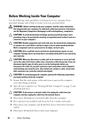
... computer, read the safety information that the work surface is not covered by periodically touching an unpainted metal surface (such as a processor by its edges, not by its pins. Do not touch the components or contacts on page 9) and all telephone or network cables... CAUTION: To avoid electrostatic discharge, ground yourself by using a wrist grounding strap or by your computer (see the Regulatory Compliance Homepage at dell.com/regulatory_compliance. Hold a component such as a connector on the cable itself. CAUTION: When you pull connectors apart, keep them evenly aligned...
... computer, read the safety information that the work surface is not covered by periodically touching an unpainted metal surface (such as a processor by its edges, not by its pins. Do not touch the components or contacts on page 9) and all telephone or network cables... CAUTION: To avoid electrostatic discharge, ground yourself by using a wrist grounding strap or by your computer (see the Regulatory Compliance Homepage at dell.com/regulatory_compliance. Hold a component such as a connector on the cable itself. CAUTION: When you pull connectors apart, keep them evenly aligned...

Service Manual
Page 80
1 1 system board 15 Turn the system board over. 16 Remove the coin-cell battery (see "Removing the Coin-Cell Battery" on page 87). 17 Follow the instructions from step 3 to step 5 in "Removing the Hard-Drive Assembly" on page 95. 18 Remove the thermal cooling assembly (see "Removing the Thermal Cooling Assembly" on page 89. 19 Remove the processor module (see "Removing the Processor Module" on page 91). 80 System Board
1 1 system board 15 Turn the system board over. 16 Remove the coin-cell battery (see "Removing the Coin-Cell Battery" on page 87). 17 Follow the instructions from step 3 to step 5 in "Removing the Hard-Drive Assembly" on page 95. 18 Remove the thermal cooling assembly (see "Removing the Thermal Cooling Assembly" on page 89. 19 Remove the processor module (see "Removing the Processor Module" on page 91). 80 System Board

Service Manual
Page 81
Replacing the System Board 1 Follow the instructions in "Before You Begin" on page 9. 2 Replace the processor module (see "Replacing the Processor Module" on page 92). 3 Replace the thermal cooling assembly (see "Replacing the Thermal Cooling Assembly" on page 90. 4 Follow the instructions from step 5 to step 7 ...
Replacing the System Board 1 Follow the instructions in "Before You Begin" on page 9. 2 Replace the processor module (see "Replacing the Processor Module" on page 92). 3 Replace the thermal cooling assembly (see "Replacing the Thermal Cooling Assembly" on page 90. 4 Follow the instructions from step 5 to step 7 ...

Service Manual
Page 90
CAUTION: Before turning on page 81). If either the processor or the heat sink is replaced, use the thermal pad provided in sequential order (indicated on the thermal cooling assembly). 4 Replace the system board (see "... remain inside the computer. 1 2 1 thermal cooling assembly 2 captive screws (7) Replacing the Thermal Cooling Assembly NOTE: The original thermal grease can be reused if the original processor and heat sink are reinstalled together.
CAUTION: Before turning on page 81). If either the processor or the heat sink is replaced, use the thermal pad provided in sequential order (indicated on the thermal cooling assembly). 4 Replace the system board (see "... remain inside the computer. 1 2 1 thermal cooling assembly 2 captive screws (7) Replacing the Thermal Cooling Assembly NOTE: The original thermal grease can be reused if the original processor and heat sink are reinstalled together.

Service Manual
Page 91
... assembly. CAUTION: Only a certified service technician should perform repairs on your computer). 21 Processor Module WARNING: Before working inside your computer, read the safety information that is not authorized by Dell is not covered by your warranty. Damage due to step 15 in "Before You Begin...comes to the system board, remove the main battery (see the Regulatory Compliance Homepage at dell.com/regulatory_compliance. Be careful not to bend the pins on the processor module. 5 Lift the processor module from step 2 to servicing that shipped with your skin can reduce the heat ...
... assembly. CAUTION: Only a certified service technician should perform repairs on your computer). 21 Processor Module WARNING: Before working inside your computer, read the safety information that is not authorized by Dell is not covered by your warranty. Damage due to step 15 in "Before You Begin...comes to the system board, remove the main battery (see the Regulatory Compliance Homepage at dell.com/regulatory_compliance. Be careful not to bend the pins on the processor module. 5 Lift the processor module from step 2 to servicing that shipped with your skin can reduce the heat ...

Service Manual
Page 92
... Begin" on the pin-1 corner of the ZIF socket. NOTE: If a new processor is not seated properly. 92 Processor Module If one or more corners of the ZIF socket, then insert the processor module. NOTE: The pin-1 corner of the processor module has a triangle that aligns with the pin-1 corner of the module are... aligned at the same height. When the processor module is properly seated, all four corners are higher than the others, the module is installed, you will receive a new thermal-cooling assembly, which will ...
... Begin" on the pin-1 corner of the ZIF socket. NOTE: If a new processor is not seated properly. 92 Processor Module If one or more corners of the ZIF socket, then insert the processor module. NOTE: The pin-1 corner of the processor module has a triangle that aligns with the pin-1 corner of the module are... aligned at the same height. When the processor module is properly seated, all four corners are higher than the others, the module is installed, you will receive a new thermal-cooling assembly, which will ...

Service Manual
Page 93
... turning the cam screw. 3 Tighten the ZIF socket by turning the cam screw clockwise to secure the processor module to the system board. 4 Replace the thermal cooling assembly (see "Replacing the Thermal Cooling Assembly" on page 90). 5 Follow the instructions from step 6 to ...
... turning the cam screw. 3 Tighten the ZIF socket by turning the cam screw clockwise to secure the processor module to the system board. 4 Replace the thermal cooling assembly (see "Replacing the Thermal Cooling Assembly" on page 90). 5 Follow the instructions from step 6 to ...

Setup Guide
Page 52
...Real Time Clock failure Video card or chip failure Processor failure Display failure See the Service Manual at support.dell.com. If this occurs, write down the beep code and contact Dell (see the Service Manual at support.dell.com/manuals for assistance. Possible system board failure ...No RAM detected NOTE: If you cannot solve your computer. INSPIRON Solving Problems This section provides troubleshooting information for your problem using the following guidelines, see "Using Support Tools" on page 56 or "Contacting Dell" on page 76) for advanced service instructions. Beep Code...
...Real Time Clock failure Video card or chip failure Processor failure Display failure See the Service Manual at support.dell.com. If this occurs, write down the beep code and contact Dell (see the Service Manual at support.dell.com/manuals for assistance. Possible system board failure ...No RAM detected NOTE: If you cannot solve your computer. INSPIRON Solving Problems This section provides troubleshooting information for your problem using the following guidelines, see "Using Support Tools" on page 56 or "Contacting Dell" on page 76) for advanced service instructions. Beep Code...

Setup Guide
Page 82
...Dell Inspiron M4110 Computer Information System chipset AMD A70M Processor types AMD Dual Core E2-3000M/ A4-3300M/3305M AMD Quad Core A6-3400M/3420M/ A8-3500M/3520M Memory module connector Memory module capacities Minimum memory Maximum memory two user-accessible SODIMM connectors 1 GB, 2 GB, and 4 GB 2 GB 8 GB 80 INSPIRON... Specifications This section provides information that you may vary by region. To launch the Dell Support Center, click Start → All Programs→ Dell→ Dell Support Center→ Launch Dell Support Center. NOTE: ...
...Dell Inspiron M4110 Computer Information System chipset AMD A70M Processor types AMD Dual Core E2-3000M/ A4-3300M/3305M AMD Quad Core A6-3400M/3420M/ A8-3500M/3520M Memory module connector Memory module capacities Minimum memory Maximum memory two user-accessible SODIMM connectors 1 GB, 2 GB, and 4 GB 2 GB 8 GB 80 INSPIRON... Specifications This section provides information that you may vary by region. To launch the Dell Support Center, click Start → All Programs→ Dell→ Dell Support Center→ Launch Dell Support Center. NOTE: ...


