
Owner's Manual
Page 139
... section, follow the safety instructions in the Product Information Guide. NOTE: Memory modules purchased from Dell are intended for information on page 129. 2 Turn the computer over. 3 Loosen the captive screws from the bottom of the computer). 1 Follow the procedures in "Before You Begin" on ... has two user-accessible SODIMM sockets, DIMM A and DIMM B accessed from the memory module cover. 4 Lift the memory module cover and set it aside. Removing the Memory Module NOTICE: To avoid electrostatic discharge, ground yourself by using a wrist grounding strap or by periodically touching an...
... section, follow the safety instructions in the Product Information Guide. NOTE: Memory modules purchased from Dell are intended for information on page 129. 2 Turn the computer over. 3 Loosen the captive screws from the bottom of the computer). 1 Follow the procedures in "Before You Begin" on ... has two user-accessible SODIMM sockets, DIMM A and DIMM B accessed from the memory module cover. 4 Lift the memory module cover and set it aside. Removing the Memory Module NOTICE: To avoid electrostatic discharge, ground yourself by using a wrist grounding strap or by periodically touching an...
Service Manual
Page 9
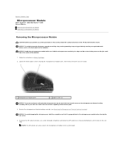
... module with care. Oils in the center of the thermal pads. 3. Loosen the three captive screws securing the microprocessor module cover, then remove the cover and set it is perpendicular to Contents Page Microprocessor Module Dell™ Inspiron™ 1420/Dell Vostro™ 1400 Service Manual Removing the Microprocessor Module Replacing the Microprocessor Module Removing the...
... module with care. Oils in the center of the thermal pads. 3. Loosen the three captive screws securing the microprocessor module cover, then remove the cover and set it is perpendicular to Contents Page Microprocessor Module Dell™ Inspiron™ 1420/Dell Vostro™ 1400 Service Manual Removing the Microprocessor Module Replacing the Microprocessor Module Removing the...

Service Manual
Page 12
... the microprocessor module cover, then remove the cover and set it aside. 1 microprocessor module cover 2 captive screws (3) 3. Follow the instructions in the Product Information Guide. NOTICE: To avoid electrostatic discharge, ground yourself by...-cooling assembly 2 screws (4) Replacing the Microprocessor Thermal-Cooling Assembly CAUTION: Before you perform any of the procedures in this section, follow the safety instructions in Before You Begin. 2. cooling assembly to Contents Page Microprocessor Thermal-Cooling Assembly Dell™ Inspiron™ 1420/Dell Vostro™ 1400...
... the microprocessor module cover, then remove the cover and set it aside. 1 microprocessor module cover 2 captive screws (3) 3. Follow the instructions in the Product Information Guide. NOTICE: To avoid electrostatic discharge, ground yourself by...-cooling assembly 2 screws (4) Replacing the Microprocessor Thermal-Cooling Assembly CAUTION: Before you perform any of the procedures in this section, follow the safety instructions in Before You Begin. 2. cooling assembly to Contents Page Microprocessor Thermal-Cooling Assembly Dell™ Inspiron™ 1420/Dell Vostro™ 1400...

Service Manual
Page 29
...connector until the module pops up. 6. Loosen the captive screws from the connector. NOTE: For optimal performance, identical memory modules should be used in Before You Begin. 2. Back to Contents Page Memory Dell™ Inspiron™ 1420/Dell Vostro™ 1400 Service Manual Removing the Memory Module ...yourself by using a wrist grounding strap or by installing memory modules on the system board. Lift the memory module cover and set it aside. 1 captive screws (3) 2 memory module cover NOTICE: To prevent damage to the memory module connector, do not use tools to avoid damaging ...
...connector until the module pops up. 6. Loosen the captive screws from the connector. NOTE: For optimal performance, identical memory modules should be used in Before You Begin. 2. Back to Contents Page Memory Dell™ Inspiron™ 1420/Dell Vostro™ 1400 Service Manual Removing the Memory Module ...yourself by using a wrist grounding strap or by installing memory modules on the system board. Lift the memory module cover and set it aside. 1 captive screws (3) 2 memory module cover NOTICE: To prevent damage to the memory module connector, do not use tools to avoid damaging ...


