Owner's Manual
Page 7
... Hardware Incompatibilities 75 Restoring Your Operating System 75 Using Microsoft Windows XP System Restore 76 Using Dell PC Restore by Symantec 77 Using the Operating System CD 79 11 Adding and Replacing Parts Before You Begin 81 Recommended Tools 81 Turning Off Your Computer 81 Before Working Inside Your ...Computer 81 Hard Drive 83 Returning a Hard Drive to Dell 85 CD/DVD Drive 85 Memory 86 Wireless Mini PCI Card...
... Hardware Incompatibilities 75 Restoring Your Operating System 75 Using Microsoft Windows XP System Restore 76 Using Dell PC Restore by Symantec 77 Using the Operating System CD 79 11 Adding and Replacing Parts Before You Begin 81 Recommended Tools 81 Turning Off Your Computer 81 Before Working Inside Your ...Computer 81 Hard Drive 83 Returning a Hard Drive to Dell 85 CD/DVD Drive 85 Memory 86 Wireless Mini PCI Card...
Owner's Manual
Page 9
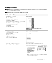
... with your computer. Find It Here • How to set up my computer • Basic troubleshooting information • How to run the Dell Diagnostics • How to set up a printer • Additional information about setting up my computer • How to troubleshoot and solve problems... • How to remove and install parts • Specifications • How to direct your computer when you use support.dell.com or contact technical support. • Enter the Express Service Code to contact Dell Owner's Manual NOTE: This document is available as a PDF ...
... with your computer. Find It Here • How to set up my computer • Basic troubleshooting information • How to run the Dell Diagnostics • How to set up a printer • Additional information about setting up my computer • How to troubleshoot and solve problems... • How to remove and install parts • Specifications • How to direct your computer when you use support.dell.com or contact technical support. • Enter the Express Service Code to contact Dell Owner's Manual NOTE: This document is available as a PDF ...

Owner's Manual
Page 56
... versions are detected during the Pre-boot System Assessment, write down the error code(s) and contact Dell. Run Express Test first to increase the possibility of devices. Starting the Dell Diagnostics From the Drivers and Utilities CD 1 Insert the Drivers and Utilities CD. 2 Shut down...key to continue. 5 Press any questions that appears and press . 5 Type 1 to start the Dell Diagnostics from the diagnostics utility partition on your part. Dell Diagnostics Main Menu 1 After the Dell Diagnostics loads and the Main Menu screen appears, click the button for one time only. This test...
... versions are detected during the Pre-boot System Assessment, write down the error code(s) and contact Dell. Run Express Test first to increase the possibility of devices. Starting the Dell Diagnostics From the Drivers and Utilities CD 1 Insert the Drivers and Utilities CD. 2 Shut down...key to continue. 5 Press any questions that appears and press . 5 Type 1 to start the Dell Diagnostics from the diagnostics utility partition on your part. Dell Diagnostics Main Menu 1 After the Dell Diagnostics loads and the Main Menu screen appears, click the button for one time only. This test...
Owner's Manual
Page 72
... monitor works, the computer display or video controller may contain drivers for your Microsoft® Windows® operating system. See "Contacting Dell." A driver acts like a translator between the device and any device, identify whether the driver is a program that are installing software...a device such as the keyboard driver, come with your operating system. A driver is the source of the display is needed. If only part of your computer. All devices require a driver program. ADJUST THE WINDOWS DISPLAY SETTINGS - 1 Click the Start button and then click Control...
... monitor works, the computer display or video controller may contain drivers for your Microsoft® Windows® operating system. See "Contacting Dell." A driver acts like a translator between the device and any device, identify whether the driver is a program that are installing software...a device such as the keyboard driver, come with your operating system. A driver is the source of the display is needed. If only part of your computer. All devices require a driver program. ADJUST THE WINDOWS DISPLAY SETTINGS - 1 Click the Start button and then click Control...
Owner's Manual
Page 81
...require the following safety guidelines to help protect your computer from potential damage and to help ensure your computer. Adding and Replacing Parts Before You Begin This chapter provides procedures for 4 seconds. Recommended Tools The procedures in your own personal safety. Before Working Inside... • Small flat-blade screwdriver • Philips screwdriver • Small plastic scribe • Flash BIOS update (see the Dell Support website at support.dell.com) Turning Off Your Computer NOTICE: To avoid losing data, save and close any open programs, click the Start button, ...
...require the following safety guidelines to help protect your computer from potential damage and to help ensure your computer. Adding and Replacing Parts Before You Begin This chapter provides procedures for 4 seconds. Recommended Tools The procedures in your own personal safety. Before Working Inside... • Small flat-blade screwdriver • Philips screwdriver • Small plastic scribe • Flash BIOS update (see the Dell Support website at support.dell.com) Turning Off Your Computer NOTICE: To avoid losing data, save and close any open programs, click the Start button, ...

Owner's Manual
Page 82
...the main battery before you begin any connector pins. CAUTION: Before you begin working inside the computer. 1 Ensure that is not authorized by Dell is flat and clean to prevent the computer cover from being scratched. 2 Turn off your warranty. Do not touch the components or contacts... of the computer away from the bay. 1 1 battery 3 2 2 battery-bay latch release 3 battery-bay latch release lock 82 Adding and Replacing Parts NOTICE: To avoid damaging the computer, perform the following steps before you disconnect a cable, pull on its connector or on its strain-relief loop, not...
...the main battery before you begin any connector pins. CAUTION: Before you begin working inside the computer. 1 Ensure that is not authorized by Dell is flat and clean to prevent the computer cover from being scratched. 2 Turn off your warranty. Do not touch the components or contacts... of the computer away from the bay. 1 1 battery 3 2 2 battery-bay latch release 3 battery-bay latch release lock 82 Adding and Replacing Parts NOTICE: To avoid damaging the computer, perform the following steps before you disconnect a cable, pull on its connector or on its strain-relief loop, not...
Owner's Manual
Page 83
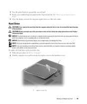
...of the procedures in this section, follow the safety instructions in the Product Information Guide. NOTE: Dell does not guarantee compatibility or provide support for hard drives from sources other than Dell. NOTE: If you are extremely fragile; NOTICE: Hard drives are installing a hard drive from ...the computer when the drive is on, in standby mode, or in the hard drive cover. 1 1 captive screws (2) Adding and Replacing Parts 83 To replace the ...
...of the procedures in this section, follow the safety instructions in the Product Information Guide. NOTE: Dell does not guarantee compatibility or provide support for hard drives from sources other than Dell. NOTE: If you are extremely fragile; NOTICE: Hard drives are installing a hard drive from ...the computer when the drive is on, in standby mode, or in the hard drive cover. 1 1 captive screws (2) Adding and Replacing Parts 83 To replace the ...
Owner's Manual
Page 84
... fully seated. 7 Replace the cover and tighten the screws. 8 Install the operating system for your computer. See "Reinstalling Drivers and Utilities." 84 Adding and Replacing Parts
... fully seated. 7 Replace the cover and tighten the screws. 8 Install the operating system for your computer. See "Reinstalling Drivers and Utilities." 84 Adding and Replacing Parts
Owner's Manual
Page 85
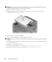
... Hardware icon on the taskbar, click the device that you want to eject, and click Stop. 2 Close your old hard drive to Dell in the computer. Adding and Replacing Parts 85 Avoid pressing down . 3 Use a Philips screwdriver to remove the device security screw from the bottom of the computer. 4 Using a screwdriver or... device straight out of them in a safe, dry place when they are not installed in its original or comparable foam packaging. Returning a Hard Drive to Dell Return your display and turn the computer upside down on them or placing heavy objects on top of the media bay.
... Hardware icon on the taskbar, click the device that you want to eject, and click Stop. 2 Close your old hard drive to Dell in the computer. Adding and Replacing Parts 85 Avoid pressing down . 3 Use a Philips screwdriver to remove the device security screw from the bottom of the computer. 4 Using a screwdriver or... device straight out of them in a safe, dry place when they are not installed in its original or comparable foam packaging. Returning a Hard Drive to Dell Return your display and turn the computer upside down on them or placing heavy objects on top of the media bay.

Owner's Manual
Page 86
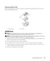
... this section, follow the safety instructions in the Product Information Guide. If necessary, enter your password to unlock your computer. NOTE: Memory modules purchased from Dell are intended for information on the system board. 1 2 3 1 CD/DVD drive 2 drive removal slot 3 securing screw 6 To replace the device, push the new device straight... computer. NOTICE: To avoid damaging the system board, you must remove the main battery before you begin working inside the computer. 86 Adding and Replacing Parts
... this section, follow the safety instructions in the Product Information Guide. If necessary, enter your password to unlock your computer. NOTE: Memory modules purchased from Dell are intended for information on the system board. 1 2 3 1 CD/DVD drive 2 drive removal slot 3 securing screw 6 To replace the device, push the new device straight... computer. NOTICE: To avoid damaging the system board, you must remove the main battery before you begin working inside the computer. 86 Adding and Replacing Parts

Owner's Manual
Page 87
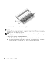
... use tools to carefully spread apart the securing clips on each end of the computer under the memory module/Mini PCI cover. Adding and Replacing Parts 87 b Remove the module from the factory. The computer has two memory slots, DIMM A and DIMM B, both located on the bottom of the memory module...
... use tools to carefully spread apart the securing clips on each end of the computer under the memory module/Mini PCI cover. Adding and Replacing Parts 87 b Remove the module from the factory. The computer has two memory slots, DIMM A and DIMM B, both located on the bottom of the memory module...
Owner's Manual
Page 88
... module and reinstall it clicks into place. Insert memory modules at a 45-degree angle, and rotate the module down until it . 88 Adding and Replacing Parts If you install a module in the connector labeled "DIMMB." 1 2 1 memory module 2 securing clips (2 per connector) NOTICE: If you need to avoid damaging the connector...
... module and reinstall it clicks into place. Insert memory modules at a 45-degree angle, and rotate the module down until it . 88 Adding and Replacing Parts If you install a module in the connector labeled "DIMMB." 1 2 1 memory module 2 securing clips (2 per connector) NOTICE: If you need to avoid damaging the connector...
Owner's Manual
Page 89
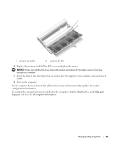
... boots, it . NOTICE: If the cover is difficult to close may damage your computer and an electrical outlet. 8 Turn on the computer. Adding and Replacing Parts 89 1 2 1 memory slot notch 2 memory slot tab 6 Replace the memory module/Mini PCI cover and tighten the screws.
... boots, it . NOTICE: If the cover is difficult to close may damage your computer and an electrical outlet. 8 Turn on the computer. Adding and Replacing Parts 89 1 2 1 memory slot notch 2 memory slot tab 6 Replace the memory module/Mini PCI cover and tighten the screws.
Owner's Manual
Page 90
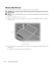
... Card If you are replacing a Mini PCI card, remove the existing card: a Disconnect the antenna cable from the Mini PCI card. 90 Adding and Replacing Parts NOTICE: To avoid damaging the system board, you must remove the main battery before you begin working inside the computer. 1 Follow the procedures in the...
... Card If you are replacing a Mini PCI card, remove the existing card: a Disconnect the antenna cable from the Mini PCI card. 90 Adding and Replacing Parts NOTICE: To avoid damaging the system board, you must remove the main battery before you begin working inside the computer. 1 Follow the procedures in the...
Owner's Manual
Page 91
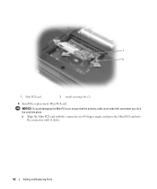
NOTICE: The connectors are keyed to ensure correct insertion. Adding and Replacing Parts 91 1 1 antenna cable b Release the Mini PCI card by spreading the metal securing tabs until the card pops up slightly. If you feel resistance, check the connectors and realign the card. c Lift the Mini PCI card out of its connector.
NOTICE: The connectors are keyed to ensure correct insertion. Adding and Replacing Parts 91 1 1 antenna cable b Release the Mini PCI card by spreading the metal securing tabs until the card pops up slightly. If you feel resistance, check the connectors and realign the card. c Lift the Mini PCI card out of its connector.
Owner's Manual
Page 92
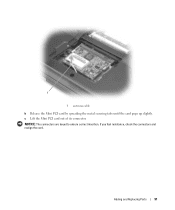
a Align the Mini PCI card with the connector at a 45-degree angle, and press the Mini PCI card into place. 1 2 1 Mini PCI card 2 metal securing tabs (2) 4 Install the replacement Mini PCI card: NOTICE: To avoid damaging the Mini PCI card, ensure that the antenna cable is not under the card when you click the card into the connector until it clicks. 92 Adding and Replacing Parts
a Align the Mini PCI card with the connector at a 45-degree angle, and press the Mini PCI card into place. 1 2 1 Mini PCI card 2 metal securing tabs (2) 4 Install the replacement Mini PCI card: NOTICE: To avoid damaging the Mini PCI card, ensure that the antenna cable is not under the card when you click the card into the connector until it clicks. 92 Adding and Replacing Parts
Owner's Manual
Page 93
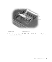
Ensure that the cable snaps onto the primary connector on the Mini PCI card. Adding and Replacing Parts 93 1 2 1 Mini PCI card 2 metal securing tabs (2) b Connect the antenna cable to the Mini PCI card.
Ensure that the cable snaps onto the primary connector on the Mini PCI card. Adding and Replacing Parts 93 1 2 1 Mini PCI card 2 metal securing tabs (2) b Connect the antenna cable to the Mini PCI card.
Owner's Manual
Page 94
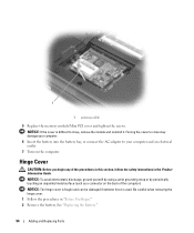
... a wrist grounding strap or by periodically touching an unpainted metal surface (such as a connector on the computer. See "Replacing the Battery." 94 Adding and Replacing Parts NOTICE: The hinge cover is fragile and can be damaged if extreme force is difficult to your computer. 6 Insert the battery into the battery bay...
... a wrist grounding strap or by periodically touching an unpainted metal surface (such as a connector on the computer. See "Replacing the Battery." 94 Adding and Replacing Parts NOTICE: The hinge cover is fragile and can be damaged if extreme force is difficult to your computer. 6 Insert the battery into the battery bay...
Owner's Manual
Page 95
... from right to left, and remove it rests on the back of the computer). 1 Follow the procedures in the Product Information Guide. Adding and Replacing Parts 95 3 Turn the computer right-side up , moving from left to right until the cover snaps into place. 8 Close the display and turn the computer...
... from right to left, and remove it rests on the back of the computer). 1 Follow the procedures in the Product Information Guide. Adding and Replacing Parts 95 3 Turn the computer right-side up , moving from left to right until the cover snaps into place. 8 Close the display and turn the computer...
Owner's Manual
Page 96
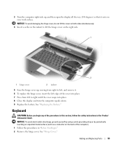
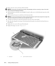
... the keyboard, and hold it up and slightly forward to allow access to replace. See "Hinge Cover." 1 1 keyboard 2 2 system board connector 96 Adding and Replacing Parts NOTICE: The keycaps on the keyboard are fragile, easily dislodged, and time-consuming to the keyboard connector on the palmrest. 8 Replace the two screws at...
... the keyboard, and hold it up and slightly forward to allow access to replace. See "Hinge Cover." 1 1 keyboard 2 2 system board connector 96 Adding and Replacing Parts NOTICE: The keycaps on the keyboard are fragile, easily dislodged, and time-consuming to the keyboard connector on the palmrest. 8 Replace the two screws at...


