

Installation Guide
Page 3
Contents 1 About This Guide Information Symbols 7 Related Publications 7 2 The E600i System System Overview 9 Install the E600i Chassis 12 3 Site Preparation Site Selection 13 Equipment Rack and Cabinet Requirements 13 Power Requirements 14 2500W AC Power Requirements 14 DC Power Requirements 14 Storage Requirements 14 4 Chassis Install the Chassis 15 Unpack the System Components 15 Install the...
Contents 1 About This Guide Information Symbols 7 Related Publications 7 2 The E600i System System Overview 9 Install the E600i Chassis 12 3 Site Preparation Site Selection 13 Equipment Rack and Cabinet Requirements 13 Power Requirements 14 2500W AC Power Requirements 14 DC Power Requirements 14 Storage Requirements 14 4 Chassis Install the Chassis 15 Unpack the System Components 15 Install the...

Installation Guide
Page 4
www.dell.com | support.dell.com 7 Installing RPMs, Line Cards, and SFMs Route Processor Modules 29 RPM LEDs 29 Line Cards 30 Line Card LEDs 30 Switch Fabric Modules 30 ... The E-Series System Boot Process 45 Booting from the BOOT_USER Prompt 45 B Alarms AC Power Supplies and Alarms 52 SFMs and Alarms 53 C System Specifications Chassis Physical Design 55 Environmental 56 4 | Contents
www.dell.com | support.dell.com 7 Installing RPMs, Line Cards, and SFMs Route Processor Modules 29 RPM LEDs 29 Line Cards 30 Line Card LEDs 30 Switch Fabric Modules 30 ... The E-Series System Boot Process 45 Booting from the BOOT_USER Prompt 45 B Alarms AC Power Supplies and Alarms 52 SFMs and Alarms 53 C System Specifications Chassis Physical Design 55 Environmental 56 4 | Contents

Installation Guide
Page 7
The E600i system operates on the Dell Force10 Operating System (FTOS) software. Information Symbols Symbol Warning ...line cards. Caution Warning This symbol informs you that could result in injury. This symbol signals information about the E600i system, refer to the FTOS Configuration Guide for the E-Series for preliminary software configuration information. Table 1-1. Information Symbols... This guide provides site preparation recommendations, instructions for rack mounting the Dell Force10 E600i ExaScale chassis, and instructions for the E-Series and FTOS About This Guide | 7
The E600i system operates on the Dell Force10 Operating System (FTOS) software. Information Symbols Symbol Warning ...line cards. Caution Warning This symbol informs you that could result in injury. This symbol signals information about the E600i system, refer to the FTOS Configuration Guide for the E-Series for preliminary software configuration information. Table 1-1. Information Symbols... This guide provides site preparation recommendations, instructions for rack mounting the Dell Force10 E600i ExaScale chassis, and instructions for the E-Series and FTOS About This Guide | 7

Installation Guide
Page 10
E600i Chassis Front View with AC Power Supplies ESD Connector Line Cards SFM3 Air Filter RPMs AC Power Supply 10 | The E600i System www.dell.com | support.dell.com Figure 2-1.
E600i Chassis Front View with AC Power Supplies ESD Connector Line Cards SFM3 Air Filter RPMs AC Power Supply 10 | The E600i System www.dell.com | support.dell.com Figure 2-1.

Installation Guide
Page 11
Figure 2-2. E600i System Component Requirements Component Backplane (factory installed) Air filter (factory installed) Fan tray RPMs Line cards SFMs Power Supplies: 2500 AC Power Supply OR DC PEMs Minimum 1 1 1 1 1 4 2 1 Maximum 1 1 1 2 7 5 4 2 Field-Replaceable N Y Y Y Y Y Y Y Grounding Holes The E600i System | 11 E600i Chassis Rear View Fan Tray Table 2-1.
Figure 2-2. E600i System Component Requirements Component Backplane (factory installed) Air filter (factory installed) Fan tray RPMs Line cards SFMs Power Supplies: 2500 AC Power Supply OR DC PEMs Minimum 1 1 1 1 1 4 2 1 Maximum 1 1 1 2 7 5 4 2 Field-Replaceable N Y Y Y Y Y Y Y Grounding Holes The E600i System | 11 E600i Chassis Rear View Fan Tray Table 2-1.
Installation Guide
Page 12
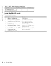
www.dell.com | support.dell.com Table 2-1. E600i System Component Requirements Component Minimum Cable management system 0 Cable management system cover 0 Maximum 1 1 Field-Replaceable Y Y Install the E600i Chassis To install the E600i system: Step Task 1 Prepare the installation site. 2 Unpack the chassis and components 3 Mount the chassis in a rack or cabinet. 4 Install the fan tray. 5 Install the power supplies, AC...
www.dell.com | support.dell.com Table 2-1. E600i System Component Requirements Component Minimum Cable management system 0 Cable management system cover 0 Maximum 1 1 Field-Replaceable Y Y Install the E600i Chassis To install the E600i system: Step Task 1 Prepare the installation site. 2 Unpack the chassis and components 3 Mount the chassis in a rack or cabinet. 4 Install the fan tray. 5 Install the power supplies, AC...

Installation Guide
Page 13
... is 30 inches deep and 24 inches wide. 4 Provide a minimum of 20 inches clearance behind the chassis to access the fan trays. 5 Air flows through the system from sources of the chassis to the appropriate branch circuit protection as hot air vents or direct sunlight. 3 The site is away ... minimum of 3 inches between the doors and the cable management system when the cabinet front doors are closed, and a minimum of 3 inches between the chassis rear and the rear of the cabinet. 3 Site Preparation This chapter describes the requirements for the room, rack, and cabinet in which you will install...
... is 30 inches deep and 24 inches wide. 4 Provide a minimum of 20 inches clearance behind the chassis to access the fan trays. 5 Air flows through the system from sources of the chassis to the appropriate branch circuit protection as hot air vents or direct sunlight. 3 The site is away ... minimum of 3 inches between the doors and the cable management system when the cabinet front doors are closed, and a minimum of 3 inches between the chassis rear and the rear of the cabinet. 3 Site Preparation This chapter describes the requirements for the room, rack, and cabinet in which you will install...

Installation Guide
Page 15
...rack. • Unpack the System Components • Install the Equipment Rack Shelf Bar • Mount the Chassis in a Rack • Mount the Chassis in a Cabinet Install the Chassis Installing the chassis is a three-step process: 1 Unpack the System Components 2 Install the Equipment Rack Shelf Bar 3 ...or foot-heal ground strap when handling system components. 1 Remove all contents from the bottom only. 4 Chassis This chapter provides instructions to rack mount your chassis into the rack and provides the unit additional support. After you remove the original packaging, place RPMs, SFMs...
...rack. • Unpack the System Components • Install the Equipment Rack Shelf Bar • Mount the Chassis in a Rack • Mount the Chassis in a Cabinet Install the Chassis Installing the chassis is a three-step process: 1 Unpack the System Components 2 Install the Equipment Rack Shelf Bar 3 ...or foot-heal ground strap when handling system components. 1 Remove all contents from the bottom only. 4 Chassis This chapter provides instructions to rack mount your chassis into the rack and provides the unit additional support. After you remove the original packaging, place RPMs, SFMs...

Installation Guide
Page 16
...Figure 4-2). 2 Orient the bar with the rack holes, and sit the chassis on top of the bar should face outward. The smooth side of the equipment rack shelf bar. 16 | Chassis Figure 4-1. www.dell.com | support.dell.com To install a equipment rack shelf bar: Step Task 1 Determine ...the chassis mounting location in a 23-inch rack, install the 23-inch adaptors. 3 Using a hand...
...Figure 4-2). 2 Orient the bar with the rack holes, and sit the chassis on top of the bar should face outward. The smooth side of the equipment rack shelf bar. 16 | Chassis Figure 4-1. www.dell.com | support.dell.com To install a equipment rack shelf bar: Step Task 1 Determine ...the chassis mounting location in a 23-inch rack, install the 23-inch adaptors. 3 Using a hand...

Installation Guide
Page 17
...Insert rack screws in the holes that are not obscured by the front shipping cover, and tighten them . Figure 4-2. Mount the Chassis in a Cabinet To install the chassis in an cabinet: Step Task 1 Install the equipment rack shelf bar. 2 Using a hand cart, pallet jack, or forklift...screws attaching the front shipping cover, and remove the cover. 5 Insert the remaining mounting screws and tighten to secure the chassis in the cabinet. Rack Mounting the Chassis 5 Remove the screws attaching the front shipping cover, and remove the cover. 6 Insert the remaining mounting screws and ...
...Insert rack screws in the holes that are not obscured by the front shipping cover, and tighten them . Figure 4-2. Mount the Chassis in a Cabinet To install the chassis in an cabinet: Step Task 1 Install the equipment rack shelf bar. 2 Using a hand cart, pallet jack, or forklift...screws attaching the front shipping cover, and remove the cover. 5 Insert the remaining mounting screws and tighten to secure the chassis in the cabinet. Rack Mounting the Chassis 5 Remove the screws attaching the front shipping cover, and remove the cover. 6 Insert the remaining mounting screws and ...

Installation Guide
Page 19
Fan Speed and Temperature Degrees Celsius Less than 25°C Between 25°C and 45°C Above 45°C Fan Speed (Low) 1800 RPM (Med) 2400 RPM (High) 3000 RPM Figure 5-1. Table 5-1. The Fan Tray Fan Tray | 19 A temperature sensor in the fan tray controls fan speed according to install and remove the chassis fan tray. • Install the Fan Tray • Remove the Fan Tray The fan tray ensures proper temperature and airflow. 5 Fan Tray This chapter provides instructions to Table 5-1.
Fan Speed and Temperature Degrees Celsius Less than 25°C Between 25°C and 45°C Above 45°C Fan Speed (Low) 1800 RPM (Med) 2400 RPM (High) 3000 RPM Figure 5-1. Table 5-1. The Fan Tray Fan Tray | 19 A temperature sensor in the fan tray controls fan speed according to install and remove the chassis fan tray. • Install the Fan Tray • Remove the Fan Tray The fan tray ensures proper temperature and airflow. 5 Fan Tray This chapter provides instructions to Table 5-1.

Installation Guide
Page 20
Never operate the system without a fully functional fan tray. www.dell.com | support.dell.com Install the Fan Tray To install the fan tray: Step Task 1 Slide the ...for up to approximately 1 minute at the top rear of the chassis. 4 If the chassis is flush with the chassis. 3 Secure the fan tray to the chassis by the handles halfway out of the chassis. 3 Place your hands under the fan tray, and pull it... completely out of the chassis. 2 Push the tray until the connector engages the backplane and the fan tray is operating, replace ...
Never operate the system without a fully functional fan tray. www.dell.com | support.dell.com Install the Fan Tray To install the fan tray: Step Task 1 Slide the ...for up to approximately 1 minute at the top rear of the chassis. 4 If the chassis is flush with the chassis. 3 Secure the fan tray to the chassis by the handles halfway out of the chassis. 3 Place your hands under the fan tray, and pull it... completely out of the chassis. 2 Push the tray until the connector engages the backplane and the fan tray is operating, replace ...

Installation Guide
Page 21
.... Power Supply Slots Power Supply Slot 1 Power Supply Slot 3 Power Supply | 21 Minimum Power Supply Requirements Power Supply Input 220VAC 110VAC DC Minimum (N) 2 3 1 Redundancy N + 1 N + 1 N + 1 The chassis has four power supply slots (Figure 6-1). WARNING: Class 1 laser product. The E600i requires a minimum of one type of two AC Power Supplies. Figure 6-1.
.... Power Supply Slots Power Supply Slot 1 Power Supply Slot 3 Power Supply | 21 Minimum Power Supply Requirements Power Supply Input 220VAC 110VAC DC Minimum (N) 2 3 1 Redundancy N + 1 N + 1 N + 1 The chassis has four power supply slots (Figure 6-1). WARNING: Class 1 laser product. The E600i requires a minimum of one type of two AC Power Supplies. Figure 6-1.
Installation Guide
Page 22
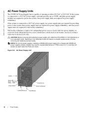
... Power Supply NOTE: Do not mix power supplies. Installing a 2500W-AC2 power supply into a chassis with 2500W-AC power supplies already installed may result in non-redundant mode will declare an alarm ... for power supply redundancy. CAUTION: Before removing and replacing a power supply unit, determine if the E600i is capable of operating at either 100 VAC or 220 VAC. If the system is connected to ...a 100 VAC power supply, each feed. Figure 6-2. www.dell.com | support.dell.com AC Power Supply Units The 2500W AC Power Supply Unit is in accordance with ...
... Power Supply NOTE: Do not mix power supplies. Installing a 2500W-AC2 power supply into a chassis with 2500W-AC power supplies already installed may result in non-redundant mode will declare an alarm ... for power supply redundancy. CAUTION: Before removing and replacing a power supply unit, determine if the E600i is capable of operating at either 100 VAC or 220 VAC. If the system is connected to ...a 100 VAC power supply, each feed. Figure 6-2. www.dell.com | support.dell.com AC Power Supply Units The 2500W AC Power Supply Unit is in accordance with ...
Installation Guide
Page 26
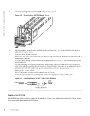
...with 1/4-inch holes on 3/4-inch spacing (see Figure 6-5). Replace the two washers and nuts. Secure the PEM to the chassis by tighten the two locking screws. 5 Secure the chassis ground connection: Remove one outer nut and one washer from each of the PEM into Power Supply Slot 1 or 3.... DsCooAunrUcoeTt pIcOlouNngn-ienUctwnioihtnim.leRaeeynmheoarvgveeizaemldlo.srueptphlyancoonnneecptoiownesr CC-E600-CVR-PEM 4 Slide the backplane connector end of the six studs. Figure 6-6. www.dell.com | support.dell.com 3 Loosen the retaining screw and remove PEM safety cover (Figure 6-6).
...with 1/4-inch holes on 3/4-inch spacing (see Figure 6-5). Replace the two washers and nuts. Secure the PEM to the chassis by tighten the two locking screws. 5 Secure the chassis ground connection: Remove one outer nut and one washer from each of the PEM into Power Supply Slot 1 or 3.... DsCooAunrUcoeTt pIcOlouNngn-ienUctwnioihtnim.leRaeeynmheoarvgveeizaemldlo.srueptphlyancoonnneecptoiownesr CC-E600-CVR-PEM 4 Slide the backplane connector end of the six studs. Figure 6-6. www.dell.com | support.dell.com 3 Loosen the retaining screw and remove PEM safety cover (Figure 6-6).

Installation Guide
Page 29
...the LEDs on port Red: a critical condition exists, such as an over -current condition in use. Press the LT button to light. Chassis slots R0 and R1 are controlled by software which sets the threshold levels for triggering the different stages of a read or write process. ... by software, which sets the threshold levels for triggering the different stages of -tolerance voltage. You can insert a second RPM into the E-Series chassis and includes the following sections: • Install RPMs, Line Cards, and SFMs • Remove RPMs, Line Cards, and SFMs Route Processor Modules...
...the LEDs on port Red: a critical condition exists, such as an over -current condition in use. Press the LT button to light. Chassis slots R0 and R1 are controlled by software which sets the threshold levels for triggering the different stages of a read or write process. ... by software, which sets the threshold levels for triggering the different stages of -tolerance voltage. You can insert a second RPM into the E-Series chassis and includes the following sections: • Install RPMs, Line Cards, and SFMs • Remove RPMs, Line Cards, and SFMs Route Processor Modules...
Installation Guide
Page 30
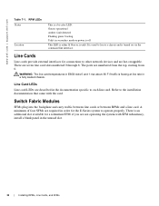
... are numbered from the top, starting from 0. Refer to locate a chassis and is a bi-color LED. Switch Fabric Modules SFMs plug into the backplane and carry traffic between line cards or between RPMs and a line card. WARNING: The line card temperatures in E600i slots 0 and 1 rise above 80 F if traffic is flowing... in the unused slot. 30 | Installing RPMs, Line Cards, and SFMs RPM LEDs Status Location This is turned on via the command line interface. www.dell.com | support.dell.com Table 7-1. Line Cards Line cards provide external interfaces for a redundant SFM;
... are numbered from the top, starting from 0. Refer to locate a chassis and is a bi-color LED. Switch Fabric Modules SFMs plug into the backplane and carry traffic between line cards or between RPMs and a line card. WARNING: The line card temperatures in E600i slots 0 and 1 rise above 80 F if traffic is flowing... in the unused slot. 30 | Installing RPMs, Line Cards, and SFMs RPM LEDs Status Location This is turned on via the command line interface. www.dell.com | support.dell.com Table 7-1. Line Cards Line cards provide external interfaces for a redundant SFM;

Installation Guide
Page 32
...Hold the card by tightening the captive screw(s) on each card. 5 Install blank panels in all unused RPM and line card slots. www.dell.com | support.dell.com Install RPMs, Line Cards, and SFMs The installation process is the same for the appropriate (RPM, line card, or SFM) slot and... connectors engage with the chassis backplane. 3 Rotate the lever(s) to seat the card in the chassis. 4 Secure card in place by the edges. Avoid touching the printed circuit board and connector pins. Extend the top and bottom card levers before you insert the card into the E600i 32 | Installing RPMs,...
...Hold the card by tightening the captive screw(s) on each card. 5 Install blank panels in all unused RPM and line card slots. www.dell.com | support.dell.com Install RPMs, Line Cards, and SFMs The installation process is the same for the appropriate (RPM, line card, or SFM) slot and... connectors engage with the chassis backplane. 3 Rotate the lever(s) to seat the card in the chassis. 4 Secure card in place by the edges. Avoid touching the printed circuit board and connector pins. Extend the top and bottom card levers before you insert the card into the E600i 32 | Installing RPMs,...

Installation Guide
Page 38
... obtain network access to the 10/100 Ethernet Management Port Configure the 10/100 Ethernet management port, labeled 10/100 Ethernet on port. www.dell.com | support.dell.com Table 8-5. Unlit: No activity 38 | RPM Ports and Cables RJ-45 to DB-25 Adapter Pin Assignments E-Series Auxiliary Port Signal DTR TxD...-45 Pinout 7 6 5 4 3 2 1 RJ-45 to DB-25 Modem Adapter DB-45 Pinout 20 3 7 7 2 8 5 Modem Signal DTR TxD GND GND RxD DCD CTS Connecting to the chassis for management functions like upgrading the FTOS image.
... obtain network access to the 10/100 Ethernet Management Port Configure the 10/100 Ethernet management port, labeled 10/100 Ethernet on port. www.dell.com | support.dell.com Table 8-5. Unlit: No activity 38 | RPM Ports and Cables RJ-45 to DB-25 Adapter Pin Assignments E-Series Auxiliary Port Signal DTR TxD...-45 Pinout 7 6 5 4 3 2 1 RJ-45 to DB-25 Modem Adapter DB-45 Pinout 20 3 7 7 2 8 5 Modem Signal DTR TxD GND GND RxD DCD CTS Connecting to the chassis for management functions like upgrading the FTOS image.
Installation Guide
Page 39
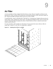
...install the filter, orient it straight out of the chassis. Inspected monthly and replace them at least every twelve months. To remove the filter, pull it so that the air filter is oriented correctly and seated securely in an E600i Air Filter | 39 The hot-swappable air filter ...the label "This Side Up" is facing upward. An improperly installed air filter restricts air flow and generates thermal problems throughout the chassis. Do not operate the chassis without a filter for longer than 3 minutes to avoid card over-temperature conditions. 9 Air Filter A factory-installed air filter is...
...install the filter, orient it straight out of the chassis. Inspected monthly and replace them at least every twelve months. To remove the filter, pull it so that the air filter is oriented correctly and seated securely in an E600i Air Filter | 39 The hot-swappable air filter ...the label "This Side Up" is facing upward. An improperly installed air filter restricts air flow and generates thermal problems throughout the chassis. Do not operate the chassis without a filter for longer than 3 minutes to avoid card over-temperature conditions. 9 Air Filter A factory-installed air filter is...


