

Installation Guide
Page 4
www.dell.com | support.dell.com 7 Installing RPMs, Line Cards, and SFMs Route Processor Modules 29 RPM LEDs 29 Line Cards 30 Line Card LEDs 30 Switch Fabric Modules 30 SFM Front Panel and LEDs 31 Blank Panels 31 Install RPMs, Line Cards, and SFMs 32 Remove RPMs, Line Cards, and SFMs 33 8 RPM Ports and Cables Connecting to the Console and Auxiliary Ports 35 Cable and Adapter Pin Assignments 35 Accessing the Console with a DB-9 Adapter 36 Accessing the Console with a DB...
www.dell.com | support.dell.com 7 Installing RPMs, Line Cards, and SFMs Route Processor Modules 29 RPM LEDs 29 Line Cards 30 Line Card LEDs 30 Switch Fabric Modules 30 SFM Front Panel and LEDs 31 Blank Panels 31 Install RPMs, Line Cards, and SFMs 32 Remove RPMs, Line Cards, and SFMs 33 8 RPM Ports and Cables Connecting to the Console and Auxiliary Ports 35 Cable and Adapter Pin Assignments 35 Accessing the Console with a DB-9 Adapter 36 Accessing the Console with a DB...

Installation Guide
Page 7
... rack mounting the Dell Force10 E600i ExaScale chassis, and instructions for preliminary software configuration information. Caution Warning This symbol informs you of data. Information Symbols Table 1-1 describes symbols contained in equipment damage or loss of important operational information. This symbol signals information about the E600i system, refer to the FTOS Configuration Guide for the E-Series for installing the fan tray, power modules, route processor modules (RPMs), switch fabric modules (SFMs), and line cards...
... rack mounting the Dell Force10 E600i ExaScale chassis, and instructions for preliminary software configuration information. Caution Warning This symbol informs you of data. Information Symbols Table 1-1 describes symbols contained in equipment damage or loss of important operational information. This symbol signals information about the E600i system, refer to the FTOS Configuration Guide for the E-Series for installing the fan tray, power modules, route processor modules (RPMs), switch fabric modules (SFMs), and line cards...

Installation Guide
Page 9
... flash memory card that can be used to input/output ports, handles packet classification (access lists, Layer 2 and Layer 3 lookups) and packet marking (DSCP or 802.1p). All traffic destined to the forwarding information tables on the line cards. Independent software images run on the RPM and directed to the E600i terminates at least four switch fabric modules (SFMs) for routing and control operations. Operating the E600i...
... flash memory card that can be used to input/output ports, handles packet classification (access lists, Layer 2 and Layer 3 lookups) and packet marking (DSCP or 802.1p). All traffic destined to the forwarding information tables on the line cards. Independent software images run on the RPM and directed to the E600i terminates at least four switch fabric modules (SFMs) for routing and control operations. Operating the E600i...

Installation Guide
Page 20
.... Remove the Fan Tray The fan tray LED lights green when the system is online and the fan tray is hot-swappable. The fan tray is operating normally. The LED lights amber in case one or more fans in the tray fail. If a fan fails, you replace the fan tray, the system operates safely for up to approximately 1 minute at the top rear of the chassis. 2 Push the tray until the connector...
.... Remove the Fan Tray The fan tray LED lights green when the system is online and the fan tray is hot-swappable. The fan tray is operating normally. The LED lights amber in case one or more fans in the tray fail. If a fan fails, you replace the fan tray, the system operates safely for up to approximately 1 minute at the top rear of the chassis. 2 Push the tray until the connector...
Installation Guide
Page 22
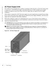
... electrical codes. CAUTION: Before removing and replacing a power supply unit, determine if the E600i is connected to a 220 VAC power supply, two power supply units are required for full facility redundancy. NOTE: Do not mix power supplies. FTOS version 8.3.1.2 and later will require a complete system power off when removing and replacing a power supply. Operating in full redundancy or non-redundant mode. four power supply units are mixed. AC Power Supply Unit Handle Status LED Green Power On Amber Fault Power Switch Thumb Screw Power Cord...
... electrical codes. CAUTION: Before removing and replacing a power supply unit, determine if the E600i is connected to a 220 VAC power supply, two power supply units are required for full facility redundancy. NOTE: Do not mix power supplies. FTOS version 8.3.1.2 and later will require a complete system power off when removing and replacing a power supply. Operating in full redundancy or non-redundant mode. four power supply units are mixed. AC Power Supply Unit Handle Status LED Green Power On Amber Fault Power Switch Thumb Screw Power Cord...
Installation Guide
Page 24
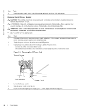
... doivent être débranchés. www.dell.com | support.dell.com Step Task 6 Toggle the power supply switch to remove all power from the socket. WARNUNG: Diese Einheit verfügt über mehr als einen Stromanschluß; all connections must be removed to the ON position, and verify that Status LED lights green. If the system is operating in the empty slot. 24 | Power Supply
... doivent être débranchés. www.dell.com | support.dell.com Step Task 6 Toggle the power supply switch to remove all power from the socket. WARNUNG: Diese Einheit verfügt über mehr als einen Stromanschluß; all connections must be removed to the ON position, and verify that Status LED lights green. If the system is operating in the empty slot. 24 | Power Supply
Installation Guide
Page 26
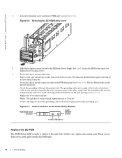
... Supply Slot 1 or 3. www.dell.com | support.dell.com 3 Loosen the retaining screw and remove PEM safety cover (Figure 6-6). Figure 6-7. Removing the DC PEM Safety Cover AbCaCArfeAtHlweaUTrkaUTseyINersOrGbrvNeei-cpf-oiVlnaTregecurerajnecsdcoaeefffresptWsyoinacwgroteuvtrenesrgrmoHuinracauelpsct.sircchuailtter DsCooAunrUcoeTt pIcOlouNngn-ienUctwnioihtnim.leRaeeynmheoarvgveeizaemldlo.srueptphlyancoonnneecptoiownesr CC-E600-CVR-PEM 4 Slide the backplane connector end of the six studs. Secure the PEM to the nearest appropriate facility grounding post. Locate the chassis...
... Supply Slot 1 or 3. www.dell.com | support.dell.com 3 Loosen the retaining screw and remove PEM safety cover (Figure 6-6). Figure 6-7. Removing the DC PEM Safety Cover AbCaCArfeAtHlweaUTrkaUTseyINersOrGbrvNeei-cpf-oiVlnaTregecurerajnecsdcoaeefffresptWsyoinacwgroteuvtrenesrgrmoHuinracauelpsct.sircchuailtter DsCooAunrUcoeTt pIcOlouNngn-ienUctwnioihtnim.leRaeeynmheoarvgveeizaemldlo.srueptphlyancoonnneecptoiownesr CC-E600-CVR-PEM 4 Slide the backplane connector end of the six studs. Secure the PEM to the nearest appropriate facility grounding post. Locate the chassis...

Installation Guide
Page 29
... • Remove RPMs, Line Cards, and SFMs Route Processor Modules The system requires at least one Route Processor Module (RPM), two RPMs provide redundancy. RPM LEDs Section Management Label 10/100 Ethernet Alarms Major Minor LT Flash Primary Description L: Green: link is lit. 7 Installing RPMs, Line Cards, and SFMs This chapter provides instructions to install cards into an online system without performance interruption or software intervention. Chassis slots R0...
... • Remove RPMs, Line Cards, and SFMs Route Processor Modules The system requires at least one Route Processor Module (RPM), two RPMs provide redundancy. RPM LEDs Section Management Label 10/100 Ethernet Alarms Major Minor LT Flash Primary Description L: Green: link is lit. 7 Installing RPMs, Line Cards, and SFMs This chapter provides instructions to install cards into an online system without performance interruption or software intervention. Chassis slots R0...
Installation Guide
Page 30
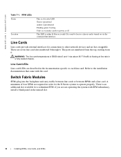
...; Switch Fabric Modules SFMs plug into the backplane and carry traffic between line cards or between RPMs and a line card. if you are seven line card slots numbered 0 through 6. Line Card LEDs Line card LEDs are hot-swappable. There is unlit. Green: operational Amber: fault detected Flashing green: booting Unlit: in a fully loaded chassis. www.dell.com | support.dell.com Table 7-1. RPM LEDs Status Location This is turned on via the command line interface. It is used to other network devices and...
...; Switch Fabric Modules SFMs plug into the backplane and carry traffic between line cards or between RPMs and a line card. if you are seven line card slots numbered 0 through 6. Line Card LEDs Line card LEDs are hot-swappable. There is unlit. Green: operational Amber: fault detected Flashing green: booting Unlit: in a fully loaded chassis. www.dell.com | support.dell.com Table 7-1. RPM LEDs Status Location This is turned on via the command line interface. It is used to other network devices and...

Installation Guide
Page 31
... same blank panel is used for empty line card and RPM slots. Table 7-2. Installing RPMs, Line Cards, and SFMs | 31 SFM Front Panel and LED Descriptions CC-E-SFM3 Active LED Active Status Description Green: active and passing traffic Unlit: in standby mode Flashing Green: booting Green: operational Flashing Amber: communication failure Amber: fault detected Unlit: no power Status Switch Fabric Assy Serial Blank Panels Blank panels are like line cards but do not have circuit boards or ejector...
... same blank panel is used for empty line card and RPM slots. Table 7-2. Installing RPMs, Line Cards, and SFMs | 31 SFM Front Panel and LED Descriptions CC-E-SFM3 Active LED Active Status Description Green: active and passing traffic Unlit: in standby mode Flashing Green: booting Green: operational Flashing Amber: communication failure Amber: fault detected Unlit: no power Status Switch Fabric Assy Serial Blank Panels Blank panels are like line cards but do not have circuit boards or ejector...

Installation Guide
Page 35
... mode must be set to NO • 24 lines X 80 characters • No flow control (console port only) • Hardware flow control (RTS/CTS) (for system configuration and monitoring. 8 RPM Ports and Cables This chapter describes standard RPM cables and adapter pin assignments. • Connecting to the Console and Auxiliary Ports • Connecting to the 10/100 Ethernet Management Port There are three ports on the RPM to connect to a terminal port...
... mode must be set to NO • 24 lines X 80 characters • No flow control (console port only) • Hardware flow control (RTS/CTS) (for system configuration and monitoring. 8 RPM Ports and Cables This chapter describes standard RPM cables and adapter pin assignments. • Connecting to the Console and Auxiliary Ports • Connecting to the 10/100 Ethernet Management Port There are three ports on the RPM to connect to a terminal port...

Installation Guide
Page 41
... a slot to accommodate an external flash memory card (slot0:). Using a Flash Memory Card | 41 Optional external flash memory cards are shipped blank. Removing the External Flash Memory Card To remove the flash memory card: Step Task 1 Extend the ejector button by pressing the ejector button. For complex configurations, use the copies for other E-Series systems in your boot execution process to use a flash card to copy the image and configuration files for storage and backup purposes. To install the flash memory card: Step...
... a slot to accommodate an external flash memory card (slot0:). Using a Flash Memory Card | 41 Optional external flash memory cards are shipped blank. Removing the External Flash Memory Card To remove the flash memory card: Step Task 1 Extend the ejector button by pressing the ejector button. For complex configurations, use the copies for other E-Series systems in your boot execution process to use a flash card to copy the image and configuration files for storage and backup purposes. To install the flash memory card: Step...

Installation Guide
Page 42
The In Use LED illuminates during a read or write operation. The default is lit. To format the flash card: Step Task 1 Insert the flash card into the flash slot on the flash card. Optional flash memory cards are shipped blank. To view the external flash, enter dir slot0: Figure 10-1. To copy files to the external flash card use the following command: Command Syntax copy file-url1 file-url2 Command Mode EXEC Privilege Purpose Configure the...
The In Use LED illuminates during a read or write operation. The default is lit. To format the flash card: Step Task 1 Insert the flash card into the flash slot on the flash card. Optional flash memory cards are shipped blank. To view the external flash, enter dir slot0: Figure 10-1. To copy files to the external flash card use the following command: Command Syntax copy file-url1 file-url2 Command Mode EXEC Privilege Purpose Configure the...

Installation Guide
Page 45
... boot problems. This mode allows you can specify the boot preference order: primary, secondary, or default in the in the BOOT_USER mode and the CLI mode. The RPM cards in non-volatile random access memory (NVRAM) to manage the boot process. Observe the process on your console monitor and note the message output on self-tests. You can copy the image files and configuration files to a 256-character remote...
... boot problems. This mode allows you can specify the boot preference order: primary, secondary, or default in the in the BOOT_USER mode and the CLI mode. The RPM cards in non-volatile random access memory (NVRAM) to manage the boot process. Observe the process on your console monitor and note the message output on self-tests. You can copy the image files and configuration files to a 256-character remote...

Installation Guide
Page 47
...boot change command to edit appropriate fields. • The primary operating system boot parameters are used if the secondary operating system boot parameter selection is not available. 4 show bootvar PRIMARY OPERATING SYSTEM BOOT PARAMETERS: boot device : flash file name : /E600i-x.bin SECONDARY OPERATING SYSTEM BOOT PARAMETERS: 5 boot change {primary | secondary | default} If your configuration displays no preconfigured operating system boot parameters, use the BACKSPACE key to correct any mistakes. BOOT_USER # show bootvar This command displays the current operating...
...boot change command to edit appropriate fields. • The primary operating system boot parameters are used if the secondary operating system boot parameter selection is not available. 4 show bootvar PRIMARY OPERATING SYSTEM BOOT PARAMETERS: boot device : flash file name : /E600i-x.bin SECONDARY OPERATING SYSTEM BOOT PARAMETERS: 5 boot change {primary | secondary | default} If your configuration displays no preconfigured operating system boot parameters, use the BACKSPACE key to correct any mistakes. BOOT_USER # show bootvar This command displays the current operating...
Installation Guide
Page 48
... to configure a gateway parameter. BOOT_USER # show interface management ethernet No IP address set for network (ftp/ tftp) operating system boot. BOOT_USER # show default-gateway Gateway IP address: 1.2.3.5 BOOT_USER # 48 | System Boot interface management ethernet ip address ip-address ip-address-mask • If the show command to view gateway default-gateway ip-address information. If your server is full-duplex and auto-negotiation. www.dell.com | support.dell.com 6 interface management port • (OPTIONAL) Use these commands to set the speed...
... to configure a gateway parameter. BOOT_USER # show interface management ethernet No IP address set for network (ftp/ tftp) operating system boot. BOOT_USER # show default-gateway Gateway IP address: 1.2.3.5 BOOT_USER # 48 | System Boot interface management ethernet ip address ip-address ip-address-mask • If the show command to view gateway default-gateway ip-address information. If your server is full-duplex and auto-negotiation. www.dell.com | support.dell.com 6 interface management port • (OPTIONAL) Use these commands to set the speed...

Installation Guide
Page 52
... card removed a. www.dell.com | support.dell.com Table B-1. Alarm Events and Reporting Module Alarm Event Line Card Hardware failure Exceeds high temperature limit Exceeds warning temperature limit Individual interface fails RPM (Non-redundant Configuration with 1 RPM) Exceeds high temperature limit Exceeds warning temperature limit RPM fails but CP is unlit. All line cards operate normally. 52 | Alarms Alarm LED major (red) major (red) minor (amber) minor (amber) Reported in event log major major minor reported Status LED on the console...
... card removed a. www.dell.com | support.dell.com Table B-1. Alarm Events and Reporting Module Alarm Event Line Card Hardware failure Exceeds high temperature limit Exceeds warning temperature limit Individual interface fails RPM (Non-redundant Configuration with 1 RPM) Exceeds high temperature limit Exceeds warning temperature limit RPM fails but CP is unlit. All line cards operate normally. 52 | Alarms Alarm LED major (red) major (red) minor (amber) minor (amber) Reported in event log major major minor reported Status LED on the console...

Installation Guide
Page 55
... Requirements • DC Power Entry Module Requirement • Agency Compliance Chassis Physical Design Parameter Specifications Height 28 inches (71.1 cm) Width 17.4 inches (44.2 cm) Depth (without cable management system) 21.5 inches (54.6 cm) Chassis weight with factory-installed components (backplane and air filter) 81 pounds (36.7 kg) Weight fully loaded (backplane, air filter, fan tray, 242 pounds (109.8 kg) SFMs, RPMs, and 7 line cards) Mounting Factory-installed rack mount...
... Requirements • DC Power Entry Module Requirement • Agency Compliance Chassis Physical Design Parameter Specifications Height 28 inches (71.1 cm) Width 17.4 inches (44.2 cm) Depth (without cable management system) 21.5 inches (54.6 cm) Chassis weight with factory-installed components (backplane and air filter) 81 pounds (36.7 kg) Weight fully loaded (backplane, air filter, fan tray, 242 pounds (109.8 kg) SFMs, RPMs, and 7 line cards) Mounting Factory-installed rack mount...
Installation Guide
Page 62
... When Opening a Support Case Managing Your Case Downloading Software Updates Technical Documentation Contact Information Log in to iSupport at http://www.force10networks.com/support/, and select the Service Request tab. • Your name, company name, phone number, and E-mail address • Preferred method of show tech-support.) • Console captures showing the error messages • Console captures showing the troubleshooting steps taken • Saved messages to a syslog server, if one is used Log...
... When Opening a Support Case Managing Your Case Downloading Software Updates Technical Documentation Contact Information Log in to iSupport at http://www.force10networks.com/support/, and select the Service Request tab. • Your name, company name, phone number, and E-mail address • Preferred method of show tech-support.) • Console captures showing the error messages • Console captures showing the troubleshooting steps taken • Saved messages to a syslog server, if one is used Log...

Installation Guide
Page 65
... specifications chassis 55 storing components 14 support contacts 61 switch recycling 60 system boot BOOT_USER 45, 46 break control sequence 45 commands ? 46 boot change 47 default-gateway 48 dir flash 49 dir slot0 49 help 46 interface management ethernet ip address 48 interface management port config 100m 48 interface management port config 10m 48 interface management port config auto- duplex 48 interface management port config no auto- Index C commands show logging eventlog 63 show tech 63 connecting auxiliary port 35 console port 35 contacting TAC (technical support...
... specifications chassis 55 storing components 14 support contacts 61 switch recycling 60 system boot BOOT_USER 45, 46 break control sequence 45 commands ? 46 boot change 47 default-gateway 48 dir flash 49 dir slot0 49 help 46 interface management ethernet ip address 48 interface management port config 100m 48 interface management port config 10m 48 interface management port config auto- duplex 48 interface management port config no auto- Index C commands show logging eventlog 63 show tech 63 connecting auxiliary port 35 console port 35 contacting TAC (technical support...


