Technical Guide
Page 4
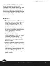
... notebook to desktop with robust hinges and latches for ultimate productivity and low total cost of document 4 LatitudeLaLEta-itFtuiatdmuedileEy5EM550a5i00n,0sEt,r5Ee45a04m000TeTcehcnhincaiclaGl Guiudiedbeobookok *See important information at every level. Latitude E5400 and E5500 notebooks deliver proven technology... for optimum performance at end of ownership. Sleek with new Latitude family docking solutions. ƒ Dell ControlPoint™ creates an awesome user experience...
... notebook to desktop with robust hinges and latches for ultimate productivity and low total cost of document 4 LatitudeLaLEta-itFtuiatdmuedileEy5EM550a5i00n,0sEt,r5Ee45a04m000TeTcehcnhincaiclaGl Guiudiedbeobookok *See important information at every level. Latitude E5400 and E5500 notebooks deliver proven technology... for optimum performance at end of ownership. Sleek with new Latitude family docking solutions. ƒ Dell ControlPoint™ creates an awesome user experience...
Technical Guide
Page 15
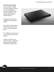
Strike Zone™ helps improve hard drive protection in the event of document 15 Sleek, Durable Design Latitude E5500 and E5400 have been designed to deliver proven technologies for improved keycap retention and screen printing on keys. Exceptional ...durability with Free Fall Sensors. Our 7200rpm hard drives now come standard with redesigned robust hinges & latches. Keyboard durability focus means E-Family is designed for everyday computing. Latitude...
Strike Zone™ helps improve hard drive protection in the event of document 15 Sleek, Durable Design Latitude E5500 and E5400 have been designed to deliver proven technologies for improved keycap retention and screen printing on keys. Exceptional ...durability with Free Fall Sensors. Our 7200rpm hard drives now come standard with redesigned robust hinges & latches. Keyboard durability focus means E-Family is designed for everyday computing. Latitude...
Technical Guide
Page 32
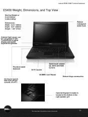
...,0E, 5E4504000TeTcehcnhincaiclaGl Guiudiedbeobookok E5400 Weight, Dimensions, and Top View Starting Weight w/ 4-cell battery: 5.42lb/2.46Kg* Dimensions: Width: 13.31"/338mm Depth: 9.61"/244mm Height: 1.46"/37mm Robust redesigned metal hook Ambient light sensor can be customized in Dell ControlPoint to adjust display... and backlit keyboard brightness Precision-tuned keyboard Hot Key to launch Dell ControlPoint console Wi-Fi Catcher Quick touch volume up, down and mute buttons SD/MMC Card Reader Robust hinge construction Optional fingerprint reader is located at the bottom of the ...
...,0E, 5E4504000TeTcehcnhincaiclaGl Guiudiedbeobookok E5400 Weight, Dimensions, and Top View Starting Weight w/ 4-cell battery: 5.42lb/2.46Kg* Dimensions: Width: 13.31"/338mm Depth: 9.61"/244mm Height: 1.46"/37mm Robust redesigned metal hook Ambient light sensor can be customized in Dell ControlPoint to adjust display... and backlit keyboard brightness Precision-tuned keyboard Hot Key to launch Dell ControlPoint console Wi-Fi Catcher Quick touch volume up, down and mute buttons SD/MMC Card Reader Robust hinge construction Optional fingerprint reader is located at the bottom of the ...

Technical Guide
Page 36
LaLtaittuitduedeE5E550500,0E, 5E4504000TeTcehcnhincaiclaGl Guiudiedbeobookok E5500 Weight, Dimensions, and Top View Starting Weight w/4-cell battery: 6.17lb/2.80Kg* Dimensions: Width: 13.99"/355mm Depth: 10.24"/260mm Height: 1.48"/37.5mm Robust redesigned metal hook Precision-tuned keyboard Wi-Fi Catcher Quick touch volume up, down and mute buttons SD/MMC Card Reader Hot Key to launch Dell ControlPoint console Robust hinge construction Optional fingerprint reader is located at the bottom of the right speaker grill *See important information at end of document 36
LaLtaittuitduedeE5E550500,0E, 5E4504000TeTcehcnhincaiclaGl Guiudiedbeobookok E5500 Weight, Dimensions, and Top View Starting Weight w/4-cell battery: 6.17lb/2.80Kg* Dimensions: Width: 13.99"/355mm Depth: 10.24"/260mm Height: 1.48"/37.5mm Robust redesigned metal hook Precision-tuned keyboard Wi-Fi Catcher Quick touch volume up, down and mute buttons SD/MMC Card Reader Hot Key to launch Dell ControlPoint console Robust hinge construction Optional fingerprint reader is located at the bottom of the right speaker grill *See important information at end of document 36
Service Manual
Page 1
... is a trademark of Dell Inc.; Blu-ray Disc is used in this text: Dell, Latitude, ExpressCharge, and the DELL logo are registered trademarks, and Core is strictly forbidden. Dell™ Latitude™ E5400 and E5500 Service Manual ...Troubleshooting Working on Your Computer Bottom of the Base Assembly Hard Drive Wireless Local Area Network (WLAN) Card Modem Card Fan Processor Heat Sink Processor Module Memory Hinge...
... is a trademark of Dell Inc.; Blu-ray Disc is used in this text: Dell, Latitude, ExpressCharge, and the DELL logo are registered trademarks, and Core is strictly forbidden. Dell™ Latitude™ E5400 and E5500 Service Manual ...Troubleshooting Working on Your Computer Bottom of the Base Assembly Hard Drive Wireless Local Area Network (WLAN) Card Modem Card Fan Processor Heat Sink Processor Module Memory Hinge...
Service Manual
Page 14
... tab next to Contents Page Display Dell™ Latitude™ E5400 and E5500 Service Manual E5400 Display Assembly E5400 Display Bezel E5400 Display Hinges E5400 Display Inverter E5400 Display Panel E5400 Display Cable E5500 Display Assembly E5500 Display Bezel E5500 Display Hinges E5500 Display Inverter E5500 Display Panel E5500 Display Cable E5400 Display Assembly Removing the E5400 Display Assembly CAUTION: Before you begin...
... tab next to Contents Page Display Dell™ Latitude™ E5400 and E5500 Service Manual E5400 Display Assembly E5400 Display Bezel E5400 Display Hinges E5400 Display Inverter E5400 Display Panel E5400 Display Cable E5500 Display Assembly E5500 Display Bezel E5500 Display Hinges E5500 Display Inverter E5500 Display Panel E5500 Display Cable E5400 Display Assembly Removing the E5400 Display Assembly CAUTION: Before you begin...

Service Manual
Page 15
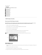
Lift the display and hinge assembly out of the computer. 1 display cable connector 2 M2.5 x 5-mm top screws (4) 3 display assembly 4 antenna cables (2) Replacing the E5400 Display Assembly CAUTION: Before you begin the following procedure, follow the safety instructions that you have completed the...assumes that shipped with the holes in the base of the computer. Replace the two M2.5 x 8-mm screws on www.dell.com at: www.dell.com/regulatory_compliance. Insert the antenna cables into place. 2. For additional safety best practices information, see the Regulatory Compliance Homepage ...
Lift the display and hinge assembly out of the computer. 1 display cable connector 2 M2.5 x 5-mm top screws (4) 3 display assembly 4 antenna cables (2) Replacing the E5400 Display Assembly CAUTION: Before you begin the following procedure, follow the safety instructions that you have completed the...assumes that shipped with the holes in the base of the computer. Replace the two M2.5 x 8-mm screws on www.dell.com at: www.dell.com/regulatory_compliance. Insert the antenna cables into place. 2. For additional safety best practices information, see the Regulatory Compliance Homepage ...

Service Manual
Page 16
... bezel. Replace the keyboard (see Replacing the Hinge Cover). 9. Remove the hinge cover (see Removing the Keyboard). 4. 1 antenna cables 6. For additional safety best practices information, see the Regulatory Compliance Homepage on Your Computer. Starting at : www.dell.com/regulatory_compliance. 1. Remove the display assembly (see Replacing the E5400 Bottom of the bezel from the top...
... bezel. Replace the keyboard (see Replacing the Hinge Cover). 9. Remove the hinge cover (see Removing the Keyboard). 4. 1 antenna cables 6. For additional safety best practices information, see the Regulatory Compliance Homepage on Your Computer. Starting at : www.dell.com/regulatory_compliance. 1. Remove the display assembly (see Replacing the E5400 Bottom of the bezel from the top...

Service Manual
Page 17
..., see the Regulatory Compliance Homepage on www.dell.com at : www.dell.com/regulatory_compliance. Follow the instructions in After Working on Your Computer. 2. NOTE: This procedure assumes that you have completed the removal procedure first. 1. Replace the hinge cover (see Removing the Hinge Cover). 3. E5400 Display Hinges Removing the E5400 Display Hinges CAUTION: Before you begin the following...
..., see the Regulatory Compliance Homepage on www.dell.com at : www.dell.com/regulatory_compliance. Follow the instructions in After Working on Your Computer. 2. NOTE: This procedure assumes that you have completed the removal procedure first. 1. Replace the hinge cover (see Removing the Hinge Cover). 3. E5400 Display Hinges Removing the E5400 Display Hinges CAUTION: Before you begin the following...

Service Manual
Page 18
...). 4. Remove the keyboard (see Replacing the E5400 Display Assembly). 4. Disconnect the two display inverter connectors. 8. Replace the keyboard (see Replacing the Hinge Cover). 6. Replace the hinge cover (see Replacing the Keyboard). 5. Follow ...E5400 Display Bezel). 6. Replace the four M2.5 x 5-mm screws (two per side) that secure the display hinges to the bezel. 1. Remove the display bezel (see Removing the Hinge Cover). 3. For additional safety best practices information, see Replacing the E5500 Display Bezel). 3. Follow the instructions in After Working on www.dell...
...). 4. Remove the keyboard (see Replacing the E5400 Display Assembly). 4. Disconnect the two display inverter connectors. 8. Replace the keyboard (see Replacing the Hinge Cover). 6. Replace the hinge cover (see Replacing the Keyboard). 5. Follow ...E5400 Display Bezel). 6. Replace the four M2.5 x 5-mm screws (two per side) that secure the display hinges to the bezel. 1. Remove the display bezel (see Removing the Hinge Cover). 3. For additional safety best practices information, see Replacing the E5500 Display Bezel). 3. Follow the instructions in After Working on www.dell...
Service Manual
Page 19
... After Working on Your Computer. 2. Remove the keyboard (see Replacing the Hinge Cover). 7. Replace the hinge cover (see Removing the Keyboard). 4. Remove the display bezel (see Removing the E5400 Display Inverter). 7. Close the display and turn the computer over. 8. Remove... information, see the Regulatory Compliance Homepage on www.dell.com at : www.dell.com/regulatory_compliance. 1. For additional safety best practices information, see the Regulatory Compliance Homepage on www.dell.com at : www.dell.com/regulatory_compliance. Remove the eight M2 x 3-mm...
... After Working on Your Computer. 2. Remove the keyboard (see Replacing the Hinge Cover). 7. Replace the hinge cover (see Removing the Keyboard). 4. Remove the display bezel (see Removing the E5400 Display Inverter). 7. Close the display and turn the computer over. 8. Remove... information, see the Regulatory Compliance Homepage on www.dell.com at : www.dell.com/regulatory_compliance. 1. For additional safety best practices information, see the Regulatory Compliance Homepage on www.dell.com at : www.dell.com/regulatory_compliance. Remove the eight M2 x 3-mm...
Service Manual
Page 20
... the display panel to the display hinge panels. 2. Replace the display inverter (see Removing the Hinge Cover). 3. For additional safety best practices information, see Removing the E5400 Display Bezel). 7. Follow the instructions in Before Working on www.dell.com at : www.dell.com/regulatory_compliance. Remove the hinge cover (see Replacing the E5400 Display Inverter). 4. Remove the four...
... the display panel to the display hinge panels. 2. Replace the display inverter (see Removing the Hinge Cover). 3. For additional safety best practices information, see Removing the E5400 Display Bezel). 7. Follow the instructions in Before Working on www.dell.com at : www.dell.com/regulatory_compliance. Remove the hinge cover (see Replacing the E5400 Display Inverter). 4. Remove the four...

Service Manual
Page 21
... the procedures in Before Working on Your Computer. Replace the display panel (see Replacing the E5400 Display Assembly). 6. Replace the display assembly (see Replacing the E5400 Display Panel). 3. Remove the hinge cover (see the Regulatory Compliance Homepage on www.dell.com at : www.dell.com/regulatory_compliance. 1. For additional safety best practices information, see Removing the...
... the procedures in Before Working on Your Computer. Replace the display panel (see Replacing the E5400 Display Assembly). 6. Replace the display assembly (see Replacing the E5400 Display Panel). 3. Remove the hinge cover (see the Regulatory Compliance Homepage on www.dell.com at : www.dell.com/regulatory_compliance. 1. For additional safety best practices information, see Removing the...

Service Manual
Page 22
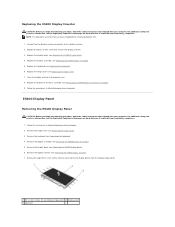
... cables through the hole in the palm rest. 9. Remove the two M2.5 x 8-mm screws on the top of the computer that secure the hinges located on the bottom of the computer. 10. Remove the antenna cables from the metal and plastic cable guides. 7. Remove the two M2.5 x ...8-mm screws that secure the metal hinges. 11. Lift the display and hinge assembly out of the computer. 8. 1 display cable 2 antenna cables 6. Turn the computer over and remove the antenna cables by moving them...
... cables through the hole in the palm rest. 9. Remove the two M2.5 x 8-mm screws on the top of the computer that secure the hinges located on the bottom of the computer. 10. Remove the antenna cables from the metal and plastic cable guides. 7. Remove the two M2.5 x ...8-mm screws that secure the metal hinges. 11. Lift the display and hinge assembly out of the computer. 8. 1 display cable 2 antenna cables 6. Turn the computer over and remove the antenna cables by moving them...
Service Manual
Page 23
Replace the two pairs of M2.5 x 8-mm hinge screws on www.dell.com at : www.dell.com/regulatory_compliance. 1. Connect the display cable to separate the remainder of the base assembly (see Replacing the Hinge Cover). 8. Replace the keyboard (see Removing the Keyboard). 4. Close the display and turn the computer over. 9. For additional safety best practices...
Replace the two pairs of M2.5 x 8-mm hinge screws on www.dell.com at : www.dell.com/regulatory_compliance. 1. Connect the display cable to separate the remainder of the base assembly (see Replacing the Hinge Cover). 8. Replace the keyboard (see Removing the Keyboard). 4. Close the display and turn the computer over. 9. For additional safety best practices...
Service Manual
Page 24
... (see Removing the E5500 Display Assembly). 5. Remove the display assembly (see Removing the Hinge Cover). 3. Remove the display bezel (see Replacing the E5500 Display Assembly). 3. For additional safety best practices information, see the Regulatory Compliance Homepage on www.dell.com at any corner, use your fingers to gently snap the bezel into...
... (see Removing the E5500 Display Assembly). 5. Remove the display assembly (see Removing the Hinge Cover). 3. Remove the display bezel (see Replacing the E5500 Display Assembly). 3. For additional safety best practices information, see the Regulatory Compliance Homepage on www.dell.com at any corner, use your fingers to gently snap the bezel into...
Service Manual
Page 25
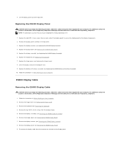
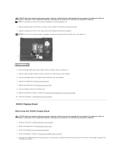
...For additional safety best practices information, see Replacing the Hinge Cover). 6. Remove the display bezel (see Replacing the E5500 Display Assembly). 4. Follow the instructions in After Working on www.dell.com at : www.dell.com/regulatory_compliance. 1. Close the display and turn the... computer over. 7. Replace the hinge cover (see the Regulatory Compliance Homepage on Your Computer. 1 M2.5 x 8-mm screws (4) 2 M2 x 3-mm screws (2) 3 hinge Replacing the E5500 Display Hinges CAUTION: Before...
...For additional safety best practices information, see Replacing the Hinge Cover). 6. Remove the display bezel (see Replacing the E5500 Display Assembly). 4. Follow the instructions in After Working on www.dell.com at : www.dell.com/regulatory_compliance. 1. Close the display and turn the... computer over. 7. Replace the hinge cover (see the Regulatory Compliance Homepage on Your Computer. 1 M2.5 x 8-mm screws (4) 2 M2 x 3-mm screws (2) 3 hinge Replacing the E5500 Display Hinges CAUTION: Before...
Service Manual
Page 26
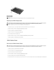
...keyboard (see Removing the E5500 Display Assembly). 5. Remove the hinge cover (see Replacing the E5500 Display Bezel). 4. Follow the instructions in After Working on www.dell.com at : www.dell.com/regulatory_compliance. For additional safety best practices information, see the ...Regulatory Compliance Homepage on Your Computer. Replace the display bezel (see Removing the Hinge Cover). 3. 8. Remove the display bezel ...
...keyboard (see Removing the E5500 Display Assembly). 5. Remove the hinge cover (see Replacing the E5500 Display Bezel). 4. Follow the instructions in After Working on www.dell.com at : www.dell.com/regulatory_compliance. For additional safety best practices information, see the ...Regulatory Compliance Homepage on Your Computer. Replace the display bezel (see Removing the Hinge Cover). 3. 8. Remove the display bezel ...

Service Manual
Page 27
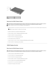
... display inverter (see the Regulatory Compliance Homepage on www.dell.com at : www.dell.com/regulatory_compliance. 1. For additional safety best practices information, see Removing the E5500 Display Inverter). 7. Replace the hinge cover (see Replacing the Keyboard). 6. E5500 Display Cable...with your computer. Replace the eight M2 x 3-mm screws (four on www.dell.com at : www.dell.com/regulatory_compliance. Replace the keyboard (see Replacing the Hinge Cover). 7. Remove the hinge cover (see Replacing the E5500 Display Assembly). 5. Replace the display assembly (see...
... display inverter (see the Regulatory Compliance Homepage on www.dell.com at : www.dell.com/regulatory_compliance. 1. For additional safety best practices information, see Removing the E5500 Display Inverter). 7. Replace the hinge cover (see Replacing the Keyboard). 6. E5500 Display Cable...with your computer. Replace the eight M2 x 3-mm screws (four on www.dell.com at : www.dell.com/regulatory_compliance. Replace the keyboard (see Replacing the Hinge Cover). 7. Remove the hinge cover (see Replacing the E5500 Display Assembly). 5. Replace the display assembly (see...
Service Manual
Page 28
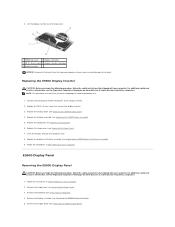
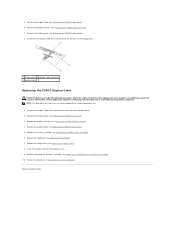
.... Connect the display cable to Contents Page Follow the procedures in After Working on www.dell.com at: www.dell.com/regulatory_compliance. Remove the display bezel (see Replacing the Hinge Cover). 8. Disconnect the display cable from the connector on the back of the base ...assembly (see Replacing the E5500 Display Assembly). 6. Replace the hinge cover (see Removing the E5500 Display Bezel). 6. ...
.... Connect the display cable to Contents Page Follow the procedures in After Working on www.dell.com at: www.dell.com/regulatory_compliance. Remove the display bezel (see Replacing the Hinge Cover). 8. Disconnect the display cable from the connector on the back of the base ...assembly (see Replacing the E5500 Display Assembly). 6. Replace the hinge cover (see Removing the E5500 Display Bezel). 6. ...


