Owner's Manual
Page 4
... Option ROM Utility 29 Recovering From a Single Hard Drive Failure Using the Intel Matrix Storage Manager 29 Setting Your Computer to RAID-Enabled Mode 30 Dell™ DataSafe (Optional 30 2 Solving Problems 31 Troubleshooting Tips 31 Battery Problems 31 Drive Problems 32 CD and DVD drive problems 32 Hard drive problems... designed for an earlier Microsoft® Windows® operating system 37 A solid blue screen appears 37 Other software problems 37 Media Card Reader Problems 38 Memory Problems 39 Mouse Problems 39 Network Problems 40 4 Contents
... Option ROM Utility 29 Recovering From a Single Hard Drive Failure Using the Intel Matrix Storage Manager 29 Setting Your Computer to RAID-Enabled Mode 30 Dell™ DataSafe (Optional 30 2 Solving Problems 31 Troubleshooting Tips 31 Battery Problems 31 Drive Problems 32 CD and DVD drive problems 32 Hard drive problems... designed for an earlier Microsoft® Windows® operating system 37 A solid blue screen appears 37 Other software problems 37 Media Card Reader Problems 38 Memory Problems 39 Mouse Problems 39 Network Problems 40 4 Contents
Owner's Manual
Page 6
Removing the Computer Cover 65 Inside View of Your Computer 67 System Board Components 68 Memory 69 DDR2 Memory Overview 69 Addressing Memory With 4-GB Configurations 70 Installing Memory 70 Removing Memory 72 Cards 73 PCI Cards 73 PCI Express Cards 77 Drive Panel 82 Removing the Drive Panel 83 Removing the Drive-Panel Insert 84...
Removing the Computer Cover 65 Inside View of Your Computer 67 System Board Components 68 Memory 69 DDR2 Memory Overview 69 Addressing Memory With 4-GB Configurations 70 Installing Memory 70 Removing Memory 72 Cards 73 PCI Cards 73 PCI Express Cards 77 Drive Panel 82 Removing the Drive Panel 83 Removing the Drive-Panel Insert 84...
Owner's Manual
Page 10
... Service Tag or product model. 3 In the Download Category drop-down menu, click All. 4 Select the operating system and operating system language for your Dell computer. as memory, the hard drive, and the operating system • Customer Care - Contact information, service call status and support history, service contract, online discussions with other...
... Service Tag or product model. 3 In the Download Category drop-down menu, click All. 4 Select the operating system and operating system language for your Dell computer. as memory, the hard drive, and the operating system • Customer Care - Contact information, service call status and support history, service contract, online discussions with other...
Owner's Manual
Page 17
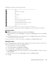
... DVDs, click Help on volume control options, click Help in the Volume Control window. Adjusting the Volume NOTE: When the speakers are using too much memory and preventing DVD playback, adjust the display properties: 1 Click the Start button and click Control Panel. 2 Under Pick a category, click Appearance and Themes. 3 Under Pick...
... DVDs, click Help on volume control options, click Help in the Volume Control window. Adjusting the Volume NOTE: When the speakers are using too much memory and preventing DVD playback, adjust the display properties: 1 Click the Start button and click Control Panel. 2 Under Pick a category, click Appearance and Themes. 3 Under Pick...
Owner's Manual
Page 20
... CD recording techniques. You can erase the data on page 99. 20 Setting Up and Using Your Computer The Media Card Reader supports the following memory types: • xD-Picture Card • SmartMedia (SMC) • CompactFlash Type I and II (CF I/II) • MicroDrive Card •... SecureDigital Card (SD) • MultiMediaCard (MMC) • Memory Stick (MS/MS Pro) For information on installing a Media Card Reader, see "Installing a Media Card Reader" on the CD-RW and try again. Using a ...
... CD recording techniques. You can erase the data on page 99. 20 Setting Up and Using Your Computer The Media Card Reader supports the following memory types: • xD-Picture Card • SmartMedia (SMC) • CompactFlash Type I and II (CF I/II) • MicroDrive Card •... SecureDigital Card (SD) • MultiMediaCard (MMC) • Memory Stick (MS/MS Pro) For information on installing a Media Card Reader, see "Installing a Media Card Reader" on the CD-RW and try again. Using a ...
Owner's Manual
Page 21
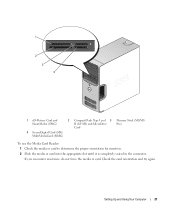
Setting Up and Using Your Computer 21 Check the card orientation and try again. 1 2 3 4 1 xD-Picture Card and SmartMedia (SMC) 2 CompactFlash Type I and 3 Memory Stick (MS/MS II (CF I/II) and MicroDrive Pro) Card 4 SecureDigital Card (SD)/ MultiMediaCard (MMC) To use the Media Card Reader: 1 Check the media or card to determine the proper orientation for insertion. 2 Slide the media or card into the appropriate slot until it is completely seated in the connector. If you encounter resistance, do not force the media or card.
Setting Up and Using Your Computer 21 Check the card orientation and try again. 1 2 3 4 1 xD-Picture Card and SmartMedia (SMC) 2 CompactFlash Type I and 3 Memory Stick (MS/MS II (CF I/II) and MicroDrive Pro) Card 4 SecureDigital Card (SD)/ MultiMediaCard (MMC) To use the Media Card Reader: 1 Check the media or card to determine the proper orientation for insertion. 2 Slide the media or card into the appropriate slot until it is completely seated in the connector. If you encounter resistance, do not force the media or card.
Owner's Manual
Page 25
... lose data. Pressing a key on the hard drive and then completely turning off the display and the hard drive after a defined period of the computer memory, Dell creates an appropriately sized hibernate mode file before shipping the computer to the state it was in certain windows. To exit from standby mode, press...
... lose data. Pressing a key on the hard drive and then completely turning off the display and the hard drive after a defined period of the computer memory, Dell creates an appropriately sized hibernate mode file before shipping the computer to the state it was in certain windows. To exit from standby mode, press...
Owner's Manual
Page 39
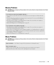
... - • Save and close any open files and exit any open programs you are following the memory installation guidelines (see "Dell Diagnostics" on cleaning the mouse. CHECK THE MOUSE CABLE - 1 Remove mouse extension cables, if used, and connect the mouse ...safety instructions in the Product Information Guide. If necessary, install additional memory (see "Installing Memory" on page 70). • Reseat the memory modules (see "Installing Memory" on page 70) to see "Dell Diagnostics" on page 109. • Run the Dell Diagnostics (see if that resolves the problem. • See the...
... - • Save and close any open files and exit any open programs you are following the memory installation guidelines (see "Dell Diagnostics" on cleaning the mouse. CHECK THE MOUSE CABLE - 1 Remove mouse extension cables, if used, and connect the mouse ...safety instructions in the Product Information Guide. If necessary, install additional memory (see "Installing Memory" on page 70). • Reseat the memory modules (see "Installing Memory" on page 70) to see "Dell Diagnostics" on page 109. • Run the Dell Diagnostics (see if that resolves the problem. • See the...
Owner's Manual
Page 41
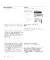
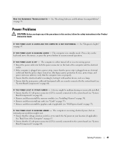
...O O T E R - I F T H E P O W E R L I G H T I N G - I F T H E P O W E R L I G H T I S B L I N K I S S T E A D Y A M B E R - The computer is securely connected to the system board (see "System Board Components" on page 68). • Remove and then reinstall the memory modules (see "PCI Express Cards" on page 70). • Remove and then reinstall any of the Computer" on page 63. • Ensure that the main...8226; Remove and then reinstall the graphics card, if applicable (see "Installing Memory" on page 77). A device might exist. • Ensure that the 12-volt power connector ...
...O O T E R - I F T H E P O W E R L I G H T I N G - I F T H E P O W E R L I G H T I S B L I N K I S S T E A D Y A M B E R - The computer is securely connected to the system board (see "System Board Components" on page 68). • Remove and then reinstall the memory modules (see "PCI Express Cards" on page 70). • Remove and then reinstall any of the Computer" on page 63. • Ensure that the main...8226; Remove and then reinstall the graphics card, if applicable (see "Installing Memory" on page 77). A device might exist. • Ensure that the 12-volt power connector ...
Owner's Manual
Page 47
... "Contacting Dell" on " outlet and press the power button. If the computer starts normally, reinstall an additional module. successfully booted to the operating system, or a possible pre-BIOS failure has occurred. Memory modules are detected, but a memory failure has occurred. • If you have ...Front View of the Computer" on page 124). To help you troubleshoot a problem, your computer (see "Installing Memory" on page 70). • If the problem persists, contact Dell (see condition after the computer "Power Problems" on page 70), and then restart the computer. Also see ...
... "Contacting Dell" on " outlet and press the power button. If the computer starts normally, reinstall an additional module. successfully booted to the operating system, or a possible pre-BIOS failure has occurred. Memory modules are detected, but a memory failure has occurred. • If you have ...Front View of the Computer" on page 124). To help you troubleshoot a problem, your computer (see "Installing Memory" on page 70). • If the problem persists, contact Dell (see condition after the computer "Power Problems" on page 70), and then restart the computer. Also see ...

Owner's Manual
Page 48
...), and then restart the computer. • If the problem still exists, install a graphics card that you have two or more memory modules installed, remove the modules, reinstall one module (see "Contacting Dell" on page 70), and then restart the computer. Continue until you are installing are detected. A possible USB failure has occurred...
...), and then restart the computer. • If the problem still exists, install a graphics card that you have two or more memory modules installed, remove the modules, reinstall one module (see "Contacting Dell" on page 70), and then restart the computer. Continue until you are installing are detected. A possible USB failure has occurred...
Owner's Manual
Page 51
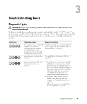
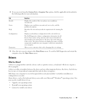
... like a translator between the device and any error conditions encountered. Describes the test and may indicate requirements for the selected device. The Dell Diagnostics obtains configuration information for more information. The device list may need to install drivers if you: • Upgrade your operating system ...driver program. You may not display the names of all the components installed on your computer or all devices from system setup, memory, and various internal tests, and it displays the information in the device list in the following table for all devices attached to ...
... like a translator between the device and any error conditions encountered. Describes the test and may indicate requirements for the selected device. The Dell Diagnostics obtains configuration information for more information. The device list may need to install drivers if you: • Upgrade your operating system ...driver program. You may not display the names of all the components installed on your computer or all devices from system setup, memory, and various internal tests, and it displays the information in the device list in the following table for all devices attached to ...
Owner's Manual
Page 68
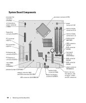
... connector (NIC) and USB connectors (2) (USB2) USB connectors (4) (USBBACK) processor connector (CPU) optional video connector (VGA) Media Card Reader connector (USBINT) power connector (12V) memory module connectors (2, 4) memory module connectors (1, 3) battery socket (BATTERY) SATA connector (SATA1) SATA connector (SATA0) front-panel connector (FRNTPANEL) SATA connector (SATA4) SATA connector (SATA5) power connector (POWER12V...
... connector (NIC) and USB connectors (2) (USB2) USB connectors (4) (USBBACK) processor connector (CPU) optional video connector (VGA) Media Card Reader connector (USBINT) power connector (12V) memory module connectors (2, 4) memory module connectors (1, 3) battery socket (BATTERY) SATA connector (SATA1) SATA connector (SATA0) front-panel connector (FRNTPANEL) SATA connector (SATA4) SATA connector (SATA5) power connector (POWER12V...
Owner's Manual
Page 69
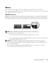
..., the computer will continue to determine the module's capacity. The recommended memory configurations are not installed in performance. DDR2 Memory Overview DDR2 memory modules should be installed in pairs of matched memory modules installed in the other connectors. A pair of DDR2 533-MHz ...and Installing Parts 69 NOTE: Always install DDR2 memory modules in DIMM connectors 3 and 4 NOTICE: Do not install ECC or buffered memory modules. Only unbuffered, non-ECC memory is supported. • If you install mixed pairs of matched memory modules installed in DIMM connectors 1 and 2...
..., the computer will continue to determine the module's capacity. The recommended memory configurations are not installed in performance. DDR2 Memory Overview DDR2 memory modules should be installed in pairs of matched memory modules installed in the other connectors. A pair of DDR2 533-MHz ...and Installing Parts 69 NOTE: Always install DDR2 memory modules in DIMM connectors 3 and 4 NOTICE: Do not install ECC or buffered memory modules. Only unbuffered, non-ECC memory is supported. • If you install mixed pairs of matched memory modules installed in DIMM connectors 1 and 2...
Owner's Manual
Page 70
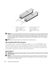
...be used by touching an unpainted metal surface on the computer chassis. 70 Removing and Installing Parts NOTE: Memory purchased from Dell is less than that you may not start properly. Certain components within the computer require address space in the 4-... connectors 3 and 4. Otherwise, your computer may have, even if you purchased the new modules from Dell. 1 2 1 Channel A: matched pair of 2 Channel B: matched pair of memory modules in memory modules in connectors DIMM_1 and connectors DIMM_3 and DIMM_2 (white securing DIMM_4 (black securing clips) clips) NOTICE...
...be used by touching an unpainted metal surface on the computer chassis. 70 Removing and Installing Parts NOTE: Memory purchased from Dell is less than that you may not start properly. Certain components within the computer require address space in the 4-... connectors 3 and 4. Otherwise, your computer may have, even if you purchased the new modules from Dell. 1 2 1 Channel A: matched pair of 2 Channel B: matched pair of memory modules in memory modules in connectors DIMM_1 and connectors DIMM_3 and DIMM_2 (white securing DIMM_4 (black securing clips) clips) NOTICE...
Owner's Manual
Page 71
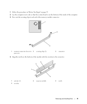
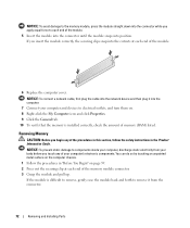
1 Follow the procedures in "Before You Begin" on page 59. 2 Lay the computer on its side so that the system board is on the bottom of the inside of the computer. 3 Press out the securing clip at each end of the memory module connector. 1 2 3 1 memory connector closest to 2 securing clips (2) processor 3 connector 4 Align the notch on the bottom of the module with the crossbar in the connector. 3 2 1 1 cutouts (2) 4 crossbar 4 2 memory module 3 notch Removing and Installing Parts 71
1 Follow the procedures in "Before You Begin" on page 59. 2 Lay the computer on its side so that the system board is on the bottom of the inside of the computer. 3 Press out the securing clip at each end of the memory module connector. 1 2 3 1 memory connector closest to 2 securing clips (2) processor 3 connector 4 Align the notch on the bottom of the module with the crossbar in the connector. 3 2 1 1 cutouts (2) 4 crossbar 4 2 memory module 3 notch Removing and Installing Parts 71
Owner's Manual
Page 72
...in "Before You Begin" on . 8 Right-click the My Computer icon and click Properties. 9 Click the General tab. 10 To verify that the memory is difficult to remove, gently ease the module back and forth to remove it into the computer. 7 Connect your computer's electronic components. NOTICE: To... You can do so by touching an unpainted metal surface on the computer chassis. 1 Follow the procedures in the Product Information Guide. Removing Memory CAUTION: Before you begin any of your computer and devices to electrical outlets, and turn them on page 59. 2 Press out the securing...
...in "Before You Begin" on . 8 Right-click the My Computer icon and click Properties. 9 Click the General tab. 10 To verify that the memory is difficult to remove, gently ease the module back and forth to remove it into the computer. 7 Connect your computer's electronic components. NOTICE: To... You can do so by touching an unpainted metal surface on the computer chassis. 1 Follow the procedures in the Product Information Guide. Removing Memory CAUTION: Before you begin any of your computer and devices to electrical outlets, and turn them on page 59. 2 Press out the securing...

Owner's Manual
Page 109
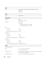
... to verify the amount of 10/100 communication 800- Appendix Specifications Processor Processor type Level 1 (L1) cache Level 2 (L2) cache Memory Type Memory connectors Memory capacities Minimum memory Maximum memory BIOS address Computer Information Chipset RAID Support DMA channels Interrupt levels BIOS chip (NVRAM) NIC System clock Intel® Pentium® 4 with ...MHz and 667-MHz dual DDR2 unbuffered SDRAM four 256 MB, 512 MB, or 1 GB non-ECC 256 MB 4 GB NOTE: See "Addressing Memory With 4-GB Configurations" on page 70 to the operating system. or 1066-MHz data rate Appendix 109
... to verify the amount of 10/100 communication 800- Appendix Specifications Processor Processor type Level 1 (L1) cache Level 2 (L2) cache Memory Type Memory connectors Memory capacities Minimum memory Maximum memory BIOS address Computer Information Chipset RAID Support DMA channels Interrupt levels BIOS chip (NVRAM) NIC System clock Intel® Pentium® 4 with ...MHz and 667-MHz dual DDR2 unbuffered SDRAM four 256 MB, 512 MB, or 1 GB non-ECC 256 MB 4 GB NOTE: See "Addressing Memory With 4-GB Configurations" on page 70 to the operating system. or 1066-MHz data rate Appendix 109
Owner's Manual
Page 110
... lanes Drives Externally accessible: Bays Available devices Internally accessible: one 3.5-inch drive bay (FlexBay) two 5.25-inch drive bays Serial ATA drives (4), floppy drive, USB memory devices, CD/DVD drive, and Media Card Reader two bays for 1-inch high serial ATA hard drives 110 Appendix
... lanes Drives Externally accessible: Bays Available devices Internally accessible: one 3.5-inch drive bay (FlexBay) two 5.25-inch drive bays Serial ATA drives (4), floppy drive, USB memory devices, CD/DVD drive, and Media Card Reader two bays for 1-inch high serial ATA hard drives 110 Appendix

Owner's Manual
Page 113
...; To change the system configuration information after you add, change, or remove any hardware in your computer • To set the type of memory or set or change the settings for your computer work incorrectly. Appendix 113 NOTE: The F2 prompt indicates that you write down your computer.... 2 When the blue DELL™ logo is recommended that the keyboard has initialized. This prompt can make your computer. System Setup Overview Use system setup as the...
...; To change the system configuration information after you add, change, or remove any hardware in your computer • To set the type of memory or set or change the settings for your computer work incorrectly. Appendix 113 NOTE: The F2 prompt indicates that you write down your computer.... 2 When the blue DELL™ logo is recommended that the keyboard has initialized. This prompt can make your computer. System Setup Overview Use system setup as the...


